Three-level rotational flow structure of afterburner head

A technology of afterburner and head, which is applied in the direction of combustion chamber, continuous combustion chamber, combustion method, etc., can solve the problems of limited size of rectifying support plate and limited size of recirculation area, so as to improve uniformity, reduce air flow velocity, The effect of accelerating the atomization process

Inactive Publication Date: 2017-05-17
NORTHWESTERN POLYTECHNICAL UNIV
View PDF6 Cites 4 Cited by
  • Summary
  • Abstract
  • Description
  • Claims
  • Application Information

AI Technical Summary

Problems solved by technology

Due to the limited size of the rectifying strut, the recirculation area provided by the concave cavity at the end of the rectifying strut is limited

Method used


Image

  • Three-level rotational flow structure of afterburner head
  • Three-level rotational flow structure of afterburner head
  • Three-level rotational flow structure of afterburner head

Examples


Embodiment Construction

[0023] The present invention will be further described now in conjunction with accompanying drawing:

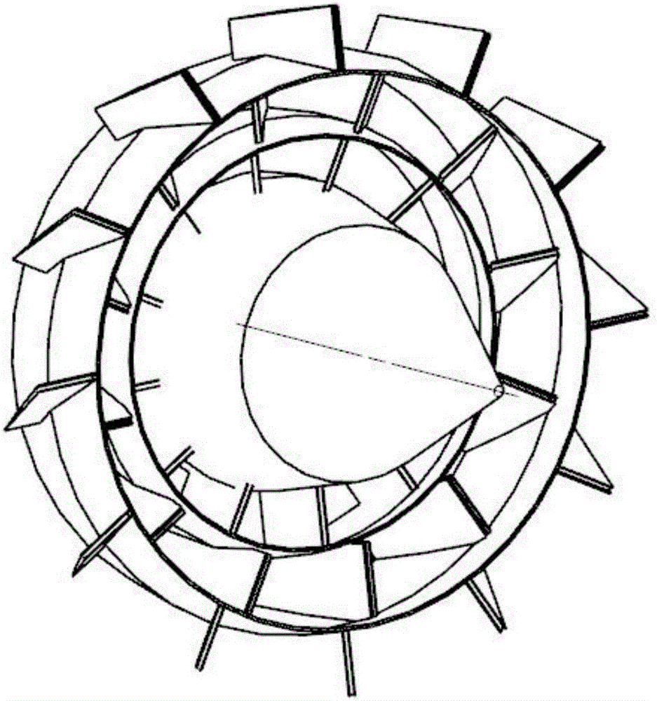
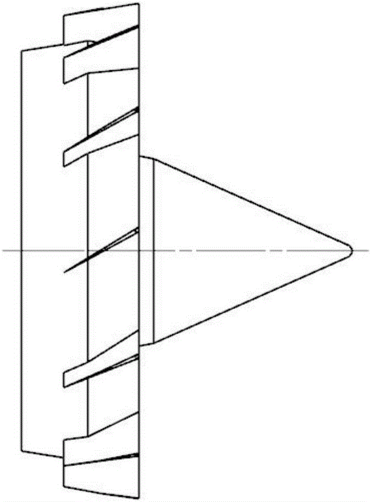
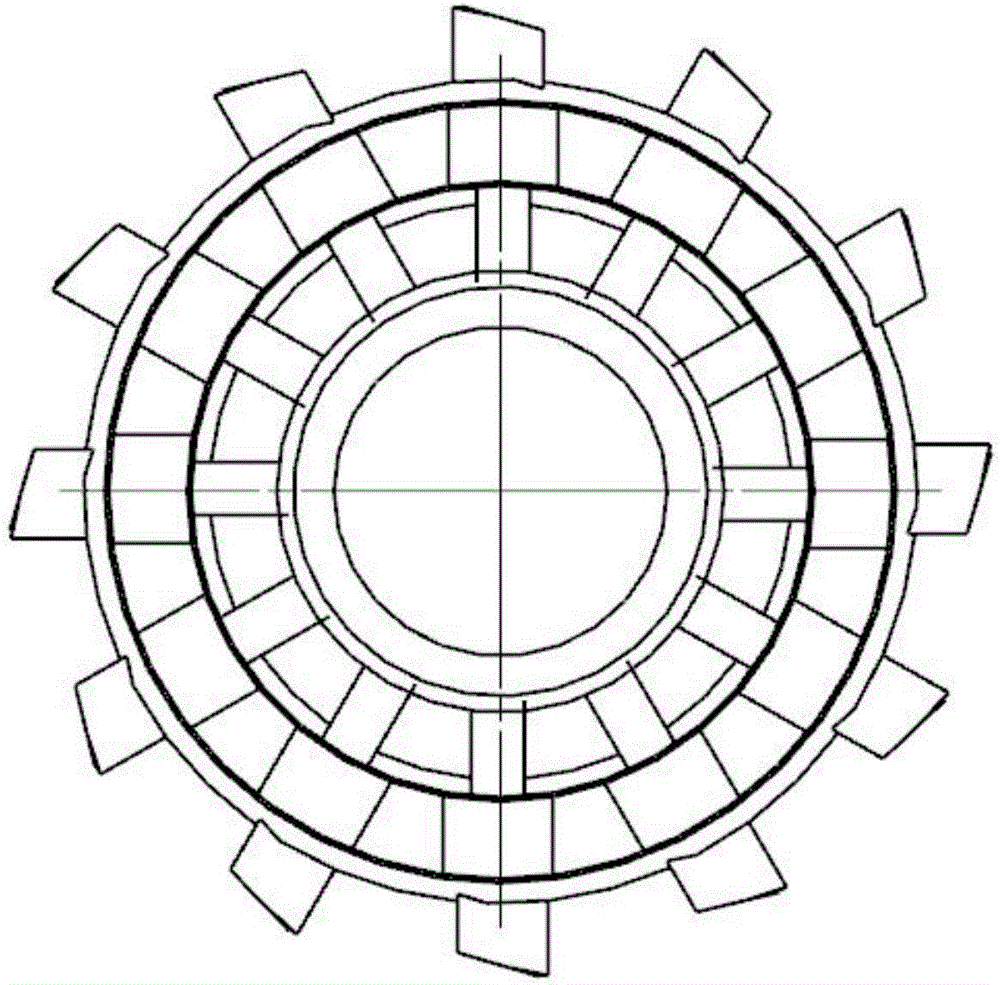
[0024] combine figure 1 , figure 2 and image 3 , The present invention provides a three-stage rectifying strut structure that can change the flow state of the inlet airflow in the afterburner and improve the combustion stability and combustion efficiency in the afterburner. figure 1 is the perspective view of the three-stage rectifier strut, figure 2 It is the side view of rectifying strut plate, image 3 It is the front view of the rectifying struts, and the height distribution of the three-stage rectifying struts can be clearly seen. Figure 4 It is a structural diagram of the entire afterburner.

[0025] In the afterburner, it is very difficult to ignite and maintain a stable flame in the combustion chamber due to the high speed of the intake air flow and the low pressure. The flame will not be blown out by the high-speed airflow, and at the same time, it can main...


PUM

PropertyMeasurementUnit
Lengthaaaaaaaaaa
Lengthaaaaaaaaaa

Abstract

The invention provides a three-level rotational flow structure of an afterburner head. A large-ranged recirculation zone can be generated by the structure in an afterburner, so that flame burning is stabilized, and meanwhile, the pressure loss can be reduced, the fuel oil atomization degree in the afterburner is reinforced, burning efficiency is improved, and the wall face can be effectively cooled; by reasonably setting the rotary angle of a whole flow supporting plate, an airflow reversely flows in a rotational-flow mode, so that shear force between fuel oil and air is increased, and the fuel oil atomization degree is improved; the flowing direction of the airflow is not suddenly changed, and thus flowing resistance is small; and an airflow rotational flow is subjected to wall-adherent movement, so that an air film is formed between the afterburner wall face and a burning zone, and the cooling effect of the afterburner wall face is guaranteed. The three-level rotational flow structure of the afterburner head has the advantages that the difficulty, caused by the over-high airflow speed in the afterburner, of igniting and maintaining stable burning of flame can be effectively improved, and the smaller pressure loss is achieved; and meanwhile, the fuel oil atomization level can be improved, and further efficient burning can be ensured.

Description

technical field [0001] The invention belongs to the field of afterburner, and in particular relates to a head structure for changing the flow state of intake air flow in the afterburner, generating swirl, and increasing the flame stability range in the afterburner Background technique [0002] The afterburner is a device that injects oil into the gas after the turbine or the mixture of gas and external content to ignite and burn, so as to increase the temperature of the airflow and increase the thrust of the engine in a short period of time. When the fighter jet starts the afterburner, the gas after the turbine enters the afterburner chamber, first decelerates and expands in the diffuser, and then mixes with the fuel injected from the nozzle to form an oil-air mixture. After the air flows through the turbine to expand and perform work, even though it is decelerated and diffused by the diffuser, compared with the main combustion chamber, the pressure is still low, the flow ra...

Claims


Application Information

Patent Timeline
IPC IPC(8): F23R3/26
CPCF23R3/26
Inventor 张群李逸飞寇睿宋亚恒李承钰黎超超
Owner NORTHWESTERN POLYTECHNICAL UNIV
Why Eureka
Try Eureka