Air conditioner equipment
A technology for air-conditioning equipment and external air-conditioning units, applied in air-conditioning systems, lighting and heating equipment, space heating and ventilation, etc., can solve problems such as user discomfort, increased fan energy consumption, poor comfort, etc., to improve thermal comfort. The effect of reducing the wind speed and uniformity of the wind
- Summary
- Abstract
- Description
- Claims
- Application Information
AI Technical Summary
Problems solved by technology
Method used
Image
Examples
Embodiment 1
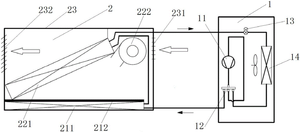
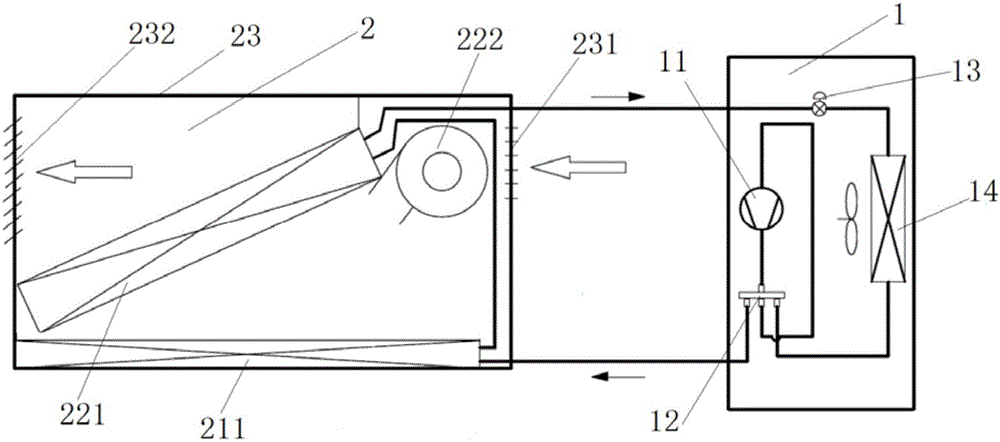
[0039] This embodiment provides an air conditioner, such as figure 1 and image 3 As shown, the air conditioner in this embodiment includes an air conditioner external unit 1 and an air conditioner internal unit 2 . Wherein, the air conditioner external unit 1 includes a compressor 11 and a third heat exchanger 14 . The air conditioner inner unit 2 includes a housing 23, a radiation heat exchange component and a convection heat exchange component. Wherein, the casing 23 is provided with an air inlet 231 and an air outlet 232 . The radiation heat exchange assembly is arranged in the casing 23 and is connected with the air conditioner external unit 1. By exchanging heat on the surface of the air conditioner internal unit 2, it forms a radiation surface to realize radiation heat exchange indoors (for example, when heating, The radiation heat exchange component heats the surface of the air conditioner inner unit 2 to form a heat radiation surface to realize radiation heat trans...
Embodiment 2
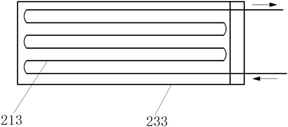
[0043] Preferably, this embodiment provides an air conditioner. Compared with the previous embodiment, on the one hand, as figure 1 and image 3 As shown, the radiation heat exchange assembly in this embodiment includes a first heat exchanger 211 . Wherein, the first heat exchanger 211 is disposed on the inner wall of the casing 23 . Preferably, the first heat exchanger 211 is disposed at a position away from the air inlet 231 and the air outlet 232 . The first heat exchanger 211 in this embodiment is a surface heat exchanger, which mainly forms a radiation surface on the surface of the housing 23 by exchanging heat on the housing 23, thereby realizing radiation heat exchange in the room (for example, When the air conditioner in this embodiment is heating, the first heat exchanger 211 is used to heat the casing 23, so that the surface of the casing 23 forms a heat radiation surface, thereby realizing radiation heat transfer to the room and improving indoor comfort ).
[00...
Embodiment 3
[0049] Preferably, this embodiment provides an air conditioner, compared with the above embodiments, such as figure 1 As shown, the radiation heat exchange assembly in this embodiment further includes a heat insulation structure 212 . Wherein, the heat insulation structure 212 is arranged in the casing 23 and is used for isolating the first heat exchanger 211 from the convective heat exchange component, the inlet and outlet, and the air outlet.
[0050] The air conditioner provided in this embodiment is provided with a heat insulation structure for separating the convective heat exchange component and the radiation heat exchange component, so that the two sets of heat exchange do not interfere with each other, thereby ensuring the radiation heat transfer capacity of the air conditioner and improving the performance of the air conditioner. Thermal comfort of the user.
[0051] Preferably, the first heat exchanger 211 in this embodiment has a first side portion and a second sid...
PUM
 Abstract
Description
Claims
Application Information
 - R&D
- Intellectual Property
- Life Sciences
- Materials
- Tech Scout
- Unparalleled Data Quality
- Higher Quality Content
- 60% Fewer Hallucinations
Browse by: Latest US Patents, China's latest patents, Technical Efficacy Thesaurus, Application Domain, Technology Topic, Popular Technical Reports.
© 2025 PatSnap. All rights reserved.Legal|Privacy policy|Modern Slavery Act Transparency Statement|Sitemap|About US| Contact US: help@patsnap.com


