
Computerized judging system and method based on three-dimensional laser vision and high-precision lane model

A three-dimensional laser, high-precision technology, applied in the direction of educational appliances, instruments, teaching aids, etc., can solve the problems of high algorithm complexity, inability to reflect the position and movement process of the target object well, and low efficiency, so as to reduce the algorithm complexity , Improving the effect of real-time computing power and practicality

Pending Publication Date: 2017-05-17
DUOLUN TECH CO LTD
View PDF10 Cites 18 Cited by
  • Summary
  • Abstract
  • Description
  • Claims
  • Application Information

AI Technical Summary

Problems solved by technology

Due to the limitations of video data, it shows the data on the two-dimensional imaging plane, lacks the depth information of the target object, and cannot well reflect the position and movement process of the target object in three-dimensional space
However, the existing vehicle-mounted laser scanning technology generally has the problems of high algorithm complexity and low efficiency in the algorithm for segmenting point cloud data, and the existing vehicle-mounted laser scanning technology cannot effectively obtain the lane where the vehicle object is located and the driving direction of the lane and other important feature information

Method used


Image

  • Computerized judging system and method based on three-dimensional laser vision and high-precision lane model
  • Computerized judging system and method based on three-dimensional laser vision and high-precision lane model
  • Computerized judging system and method based on three-dimensional laser vision and high-precision lane model

Examples


Embodiment Construction

[0045] Below in conjunction with accompanying drawing and specific embodiment, further illustrate the present invention, should be understood that these examples are only for illustrating the present invention and are not intended to limit the scope of the present invention, after having read the present invention, those skilled in the art will understand various aspects of the present invention All modifications of the valence form fall within the scope defined by the appended claims of the present application.

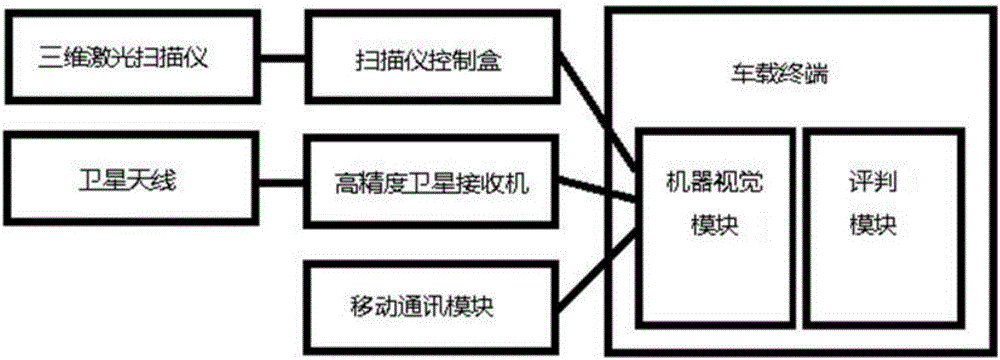
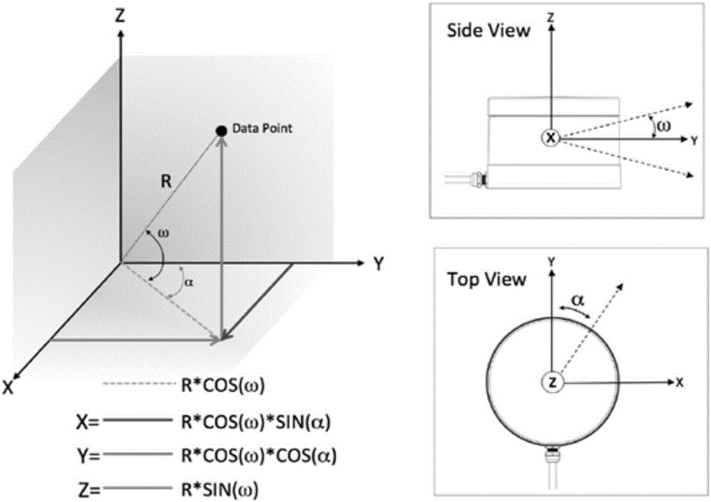
[0046] Such as figure 1 , 11As shown, a computer evaluation system based on 3D laser vision and high-precision lane model is installed on a driving test vehicle, including a vehicle terminal, a scanner control box, a satellite antenna, a high-precision satellite receiver, and a 3D vehicle mounted on the roof. Laser scanner and mobile communication module, high-precision satellite receiver is the satellite receiver of horizontal precision at 1cm+1ppm, and the high-pr...


PUM


Abstract

The invention discloses a computerized judging system and method based on three-dimensional laser vision and high-precision lane model; the system installed on a driving test vehicle comprises an embedded vehicular terminal, a mobile communication module, a three-dimensional laser scanner and a high-precision satellite receiver; the vehicular terminal operates a machine vision module and judging module based on three-dimensional laser scanning and high-precision lane model; the vehicular terminal downloads the high-precision lane model in real time through the mobile communication module, recognizes vehicles and passengers through the vision module, judges distances and speed, judges whether driver's behaviors, in case of meeting, overtaking and passengers passing by ahead, are standard or not in conjunction with the judging module so as to obtain corresponding test scores. Targets to passengers and vehicles are recognized and traced through fusion computing of three-dimensional laser scanning and high-precision lane model, positional and speed information of target objects around a vehicle, in three-dimensional space, can be reflected more precisely, and judgment related to vehicles and passengers around, unable to be achieved in the traditional driver actual road test system, is achieved according to the judging module.

Description

technical field [0001] The invention relates to a driver computer automatic test method and system, belonging to the field of vehicle-mounted computer vision. Background technique [0002] The driver computer automatic test equipment is a kind of vehicle-mounted electronic equipment installed on the test vehicle of the driver test center. Candidate test scores. Existing subject three actual road test equipment does not have the function of identifying pedestrians and vehicles around the vehicle during driving, so many evaluation functions cannot be realized, such as keeping a safe distance from surrounding vehicles during meeting, overtaking and normal driving. Whether to slow down when pedestrians and so on. [0003] Pedestrian and vehicle target recognition and tracking technology, as a computer vision technology, is of great significance in the fields of safety assisted driving and other fields. In the research of target recognition and tracking problems, video data is...

Claims


Application Information

Patent Timeline
IPC IPC(8): G09B19/16
CPCG09B19/167
Inventor 刘海青
Owner DUOLUN TECH CO LTD
Learn More