
Spiral CT scanning and image-forming method and system

A technology of helical scanning and CT scanning, applied in the field of CT scanning, can solve problems such as rising equipment prices

Active Publication Date: 2017-05-24
CHONGQING UNIV
View PDF5 Cites 6 Cited by
  • Summary
  • Abstract
  • Description
  • Claims
  • Application Information

AI Technical Summary

Problems solved by technology

Generally speaking, the third-generation scanning method of CT has higher scanning efficiency than the second-generation scanning method, but because the detector needs to fully cover the measured object in the third-generation layout method, many detectors need to be arranged to detect large-sized workpieces. unit, which directly leads to an increase in equipment prices

Method used


Image

  • Spiral CT scanning and image-forming method and system
  • Spiral CT scanning and image-forming method and system
  • Spiral CT scanning and image-forming method and system

Examples


Embodiment approach

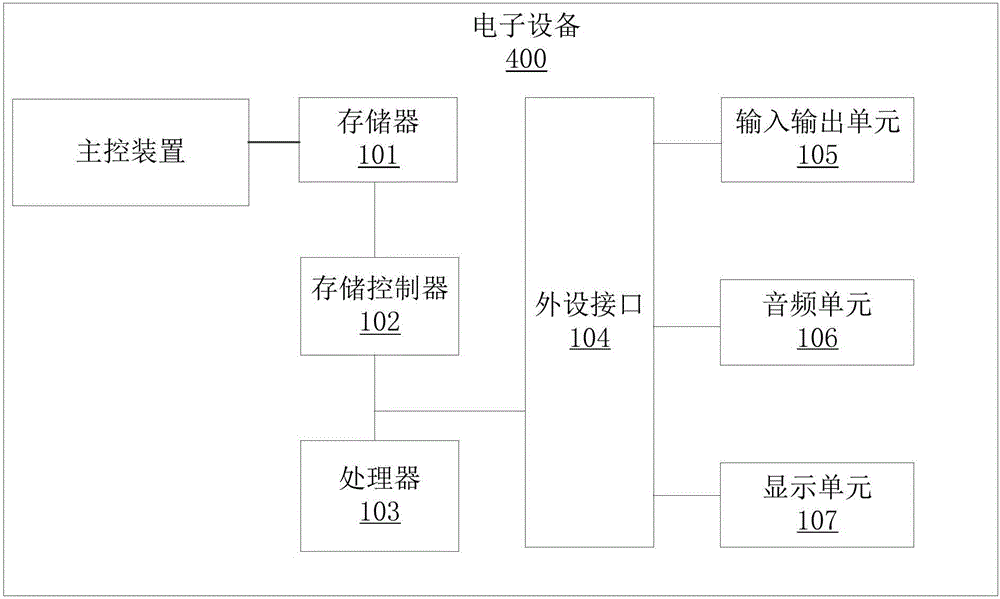
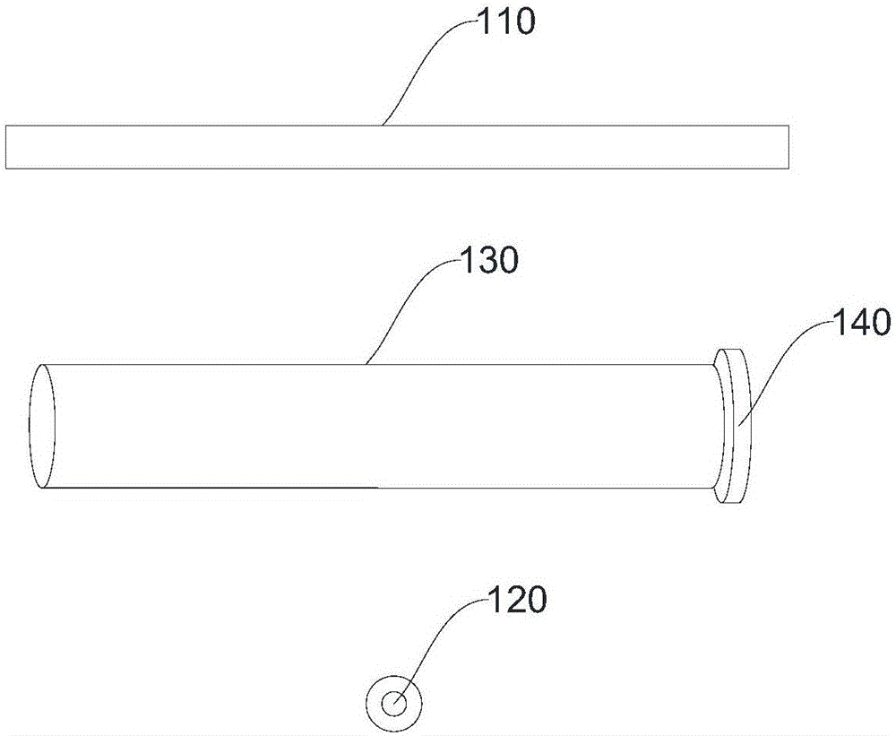
[0063] As an implementation manner, the main control device 150 includes: a translation module, an angle acquisition module, a setting module and a reconstruction module.

[0064] The translation module is used to control the ray source 120 and the detector 110 to translate a preset distance along a preset translation direction synchronously.

[0065] An angle acquisition module, configured to obtain the angle of the scanning turntable 140 according to the distance between two adjacent detection units, the number of times the radiation source 120 and the detector 110 perform helical scanning movements, and the diameter of the scanning area. deflection angle.

[0066] The setting module is configured to set the start time of the second synchronous scanning movement of the radiation source 120 and the detector 110 according to the deflection angle of the scanning turntable 140 .

[0067] The reconstruction module is used for performing CT image reconstruction on the rearranged ...


PUM


Abstract

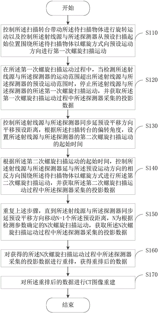
The embodiment of the invention provides a spiral CT scanning and image-forming method and system, and belongs to the technical field of CT scanning. The method comprises the following steps: controlling a detector and a ray source to perform primary spiral scanning motion and enabling a scanning rotary table to perform rotational motion; stopping motion of the ray source and the detector when the motion range of the detected ray source and the detector exceeds preset motion range; controlling the ray source and the detector to horizontally move by preset distance in the preset horizontal-moving direction, and setting starting time for secondary spiral scanning motion of the ray source and the detector according to the deflection angle of the scanning rotary table; controlling the ray source and the detector to perform secondary spiral scanning motion in a direction reverse to the preset motion direction; obtaining projection data by moving the ray source and the detector by N-1 preset distances in the preset horizontal moving direction; re-arranging the projection data; performing CT image re-construction on data, and realizing scanning on large objects through synchronous movement of the ray source and the detector. The spiral CT scanning and image-forming method reduces cost of the detector and improves scanning efficiency.

Description

technical field [0001] The present invention relates to the technical field of CT scanning, in particular to a spiral CT scanning imaging method and system. Background technique [0002] Limited by the size and cost of detectors, the main layout of large-scale high-energy industrial CT equipment is still Generation II, Generation III or Generation II+III. The detectors are basically single-row or multi-row linear array detectors, so the detection The efficiency is low and the cost of detection is high. In order to reduce crosstalk between detectors, high-energy CT generally passes through a "tunnel-type" collimator to collimate the rays before the ray source enters the detector, because each detection unit needs to have a corresponding collimator However, objectively, the number of detectors per unit length is small, the cost of a single detector is high, and large-scale integration cannot be carried out. However, without increasing the detection density, in order to impro...

Claims


Application Information

Patent Timeline
IPC IPC(8): A61B6/03
Inventor 沈宽李嘉欣陈嘉威曾理
Owner CHONGQING UNIV
Learn More