Method for preventing collision between radiotherapy machine head and therapy bed

A treatment machine and treatment couch technology, which is applied in the field of radiotherapy technology and its application, can solve the problems such as head collision of the treatment couch treatment machine, and achieve the effect of facilitating clinical application, reducing workload and reducing treatment time

Inactive Publication Date: 2017-05-24
FUDAN UNIV SHANGHAI CANCER CENT
View PDF2 Cites 8 Cited by
  • Summary
  • Abstract
  • Description
  • Claims
  • Application Information

AI Technical Summary

Problems solved by technology

[0002] In radiotherapy, with the popularization and application of isocentric treatment, due to the different positions of tumor target areas, the radiotherapy center may not necessarily be on the central axis of the patient's body, and needs to cooperate with the treatment bed to move left and right or up and down. , a collision between the treatment bed or the patient and the head of the treatment machine may occur

Method used


Image

  • Method for preventing collision between radiotherapy machine head and therapy bed
  • Method for preventing collision between radiotherapy machine head and therapy bed
  • Method for preventing collision between radiotherapy machine head and therapy bed

Examples


Embodiment 1

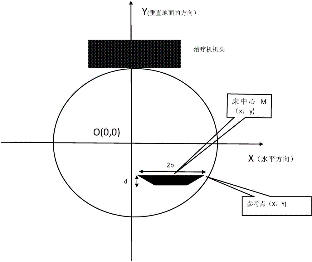
[0021] Take the isocenter of the linear accelerator as the center of the circle, and the distance from the plane where the lower edge of the treatment machine head is located to the isocenter is the radius R, and make a circle. Return the left and right displacement of the treatment bed to zero, and the up and down displacement to zero, measure the distance R from the isocenter to the plane where the lower edge of the treatment machine head is located, and measure the width of the bed. A straight line perpendicular to the ground direction and passing through the isocenter is used as the Y axis, and a straight line parallel to the ground direction and passing through the isocenter is used as the X axis to establish a rectangular coordinate system. Whether the treatment couch will collide with the lower edge of the treatment machine head is determined by judging whether the point on the treatment bed farthest from the isocenter, that is, the reference point, will collide with the...

Embodiment 2

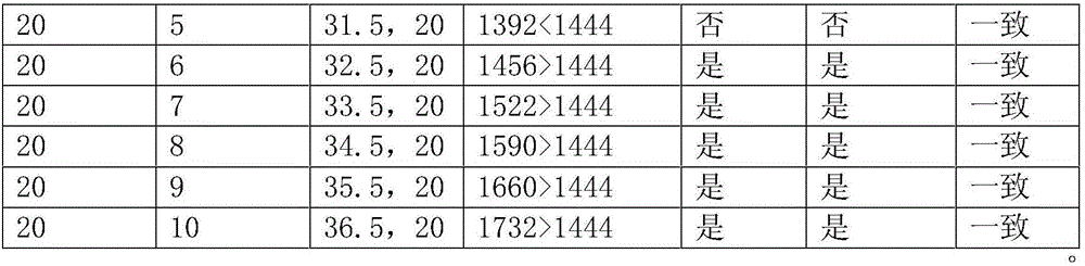
[0034] The basic principle is as follows. In the Cartesian coordinate system, if the coordinates of the center of the circle are (0,0) and the coordinates of the reference point are (X,Y), then the reference point and the circle X 2 +Y 2 =R 2 The location of is in accordance with the following relationship:

[0035] ⑴ When X 2 +Y 2 >R 2 , the reference point is outside the circle.

[0036] ⑵ When X 2 +Y 2 =R 2 , the reference point is on the circle.

[0037] ⑶ When X 2 +Y 2 2 , the reference point is inside the circle.

[0038] Specifically on the accelerator, when the width of the treatment bed is 2b, and the thickness of the treatment bed is d (the thickness of the bed needs to be considered when the cross-section of the bed is rectangular), the offset of the treatment bed in the left and right directions during treatment is x, and the treatment bed During treatment, the offset in the up and down direction is y, and the distance between the isocenter and the cent...


PUM


Abstract

The invention belongs to the field of radiotherapy technology application, and relates to a method for preventing collision between a therapy machine head and a therapy bed in the radiotherapy process. In the method, the point furthest from the equal center point in the therapy bed is used as a reference point by adopting a method of judging the position relation between a point and a circle in a standard equation of the circle, and whether the therapy bed collides with the therapy machine head is prejudged by judging the position relation between the reference point and the circle encircled by the rotating radii of the machine head. Using results show that the method is simple to implement and reliable in precision, facilitates clinical application, and can be integrated in the existing radiotherapy planning system, thereby greatly reducing the workload of technicians, reducing the radiation to the technicians, simultaneously shortening the therapy time and reducing the probability of position movement caused by intolerance of patients.

Description

technical field [0001] The invention belongs to the field of radiotherapy technology and its application, and relates to a method for preventing the collision of a treatment machine head and a treatment couch by using a standard equation of a circle in radiotherapy. This method can simply judge whether the treatment bed will collide with the handpiece. Background technique [0002] In radiotherapy, with the popularization and application of isocentric treatment, due to the different positions of tumor target areas, the radiotherapy center may not necessarily be on the central axis of the patient's body, and needs to cooperate with the treatment bed to move left and right or up and down. , a collision between the treatment bed or the patient and the treatment machine head may occur. In order to prevent collisions, it is usually necessary for the technician to idle the machine head in the machine room or enter the machine room to rotate the machine head at every angle during ...

Claims


Application Information

Patent Timeline
Patent Type & Authority Applications(China)
IPC IPC(8): A61N5/10
CPCA61N5/1048A61N5/103A61N2005/1074A61N2005/1089A61N2005/1092
Inventor 孙福厚胡伟刚许青陆维
Owner FUDAN UNIV SHANGHAI CANCER CENT
Why Eureka
Try Eureka