
High-efficiency deslagging device and high-efficiency deslagging system

A high-efficiency and equipment technology, applied in separation methods, filtration separation, chemical instruments and methods, etc., can solve the problems of eutrophication of water bodies, pollution of receiving water bodies, adverse effects on life, etc., to reduce investment costs, improve the environment, and improve The effect of sewage removal efficiency

Inactive Publication Date: 2017-05-24
英泰格润环保科技(天津)有限公司
View PDF12 Cites 3 Cited by
  • Summary
  • Abstract
  • Description
  • Claims
  • Application Information

AI Technical Summary

Problems solved by technology

[0003] However, the direct discharge not only seriously pollutes the receiving water body, affects the growth and reproduction of aquatic organisms, causes eutrophication of the water body, but also adversely affects people's lives, restricting the sustainable development of the city.

Method used


Image

  • High-efficiency deslagging device and high-efficiency deslagging system
  • High-efficiency deslagging device and high-efficiency deslagging system
  • High-efficiency deslagging device and high-efficiency deslagging system

Examples


no. 1 example

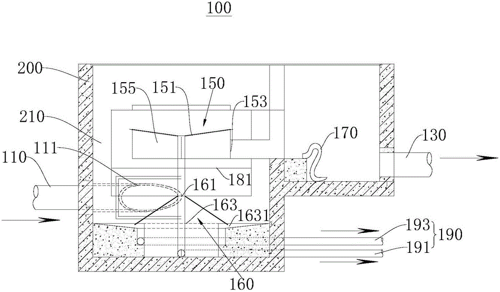
[0032] figure 1It is a structural schematic diagram of the first viewing angle of the high-efficiency slag removal equipment 100 provided by the first embodiment of the present invention. The high-efficiency slag removal equipment 100 provided in this embodiment is mainly used in sewage discharge; especially in the rainwater combined discharge system in cities, it can filter and remove slag from the rainwater overflow situation in stormy weather, and can simultaneously clean the water in the equipment. The filter assembly 150 is repeatedly backwashed to achieve the self-cleaning function, and collects and treats the pollutants in the sewage to avoid polluting the downstream water body, thereby improving the surrounding environment. In this embodiment, the description is made using the situation of rainwater overflow in rainstorm weather.

[0033] see figure 1 The high-efficiency slag removal equipment 100 provided by the first embodiment of the present invention is mainly us...

no. 2 example

[0052] Figure 4 It is a schematic structural diagram of a high-efficiency slag removal system 300 provided in the second embodiment of the present invention. see Figure 4 , the high-efficiency slag removal system 300 provided in this embodiment includes the high-efficiency slag removal equipment 100 provided in the first embodiment. The high-efficiency slag removal equipment 100 provided in this embodiment has the same basic structure and working principle as that of the first embodiment. For brief description, for parts not mentioned in this embodiment, reference may be made to the corresponding content in the first embodiment.

[0053] In this embodiment, the high-efficiency slag removal system 300 includes high-efficiency slag removal equipment 100, a confluence pipe 310, a water inlet well 330, and a sewage well 350. The confluence pipe 310 is connected and communicated with the sewage assembly 190 .

[0054] The high-efficiency slag removal system 300 provided by thi...


PUM


Abstract

The invention provides a high-efficiency deslagging device and a high-efficiency deslagging system, and mainly relates to the technical field of water treatment system. The high-efficiency deslagging device comprises a water inlet pipe, a water outlet pipe, a filter assembly, a sewage discharge assembly and a backwashing assembly, and is mainly applied in a sewage discharge channel; an accommodating cavity is formed in the discharge channel; the water inlet pipe communicates with the accommodating cavity; the filter assembly is arranged in the accommodating cavity and communicates with the backwashing assembly; the backwashing assembly is connected with and communicates with the water outlet pipe; the backwashing assembly is used for selectively increasing the liquid level in the filter assembly for backwashing the filter assembly, or reducing the liquid level in the filter assembly for making the filter assembly filter a liquid. The high-efficiency deslagging device provided by the invention can make the filter assembly inside the device perform repeated backwashing so as to achieve a self-cleaning function. The high-efficiency deslagging system also provided by the invention not only reduces the investment cost, but also improves the deslagging efficiency of sewage.

Description

technical field [0001] The invention relates to the technical field of water treatment systems, in particular to a high-efficiency slag removal equipment and a high-efficiency slag removal system. Background technique [0002] At present, most of the water supply and drainage systems in cities are combined drainage systems. In stormy weather, when the flow in the combined drainage system exceeds the sewage interception flow, the excess rain and sewage mixed sewage will be directly discharged into the receiving water body. Known as combined pipe overflow. Today, the drainage system of quite a few cities is still dominated by the combined system, and pipe overflows often occur when it rains. The current treatment methods for pipeline overflow are only to build storage tanks and increase the interception multiple, or to discharge the overflow sewage directly into the downstream water body. [0003] However, the direct discharge not only seriously pollutes the receiving water ...

Claims


Application Information

Patent Timeline
Patent Type & Authority Applications(China)
IPC IPC(8): B01D36/04B01D29/68
CPCB01D29/68B01D36/045
Inventor 罗浩郭曦齐洁白瑞峰詹璨张俊熊黎海燕张亚宁王文凤刘旭张艳红孙亮
Owner 英泰格润环保科技(天津)有限公司
Learn More