Automatic desoldering and detinning equipment

An automatic and equipment technology, applied in welding equipment, metal processing equipment, metal processing, etc., can solve the problems of circuit board scrapping, cost loss, environmental pollution, etc., and achieve the effect of thorough tin removal, high safety and wide application range

Pending Publication Date: 2017-05-24
东莞市崴泰电子有限公司
View PDF0 Cites 11 Cited by
  • Summary
  • Abstract
  • Description
  • Claims
  • Application Information

AI Technical Summary

Problems solved by technology

Due to the current manual operation method, the method of using the electric soldering iron tip to suck the tin strip is used to perform contact desoldering operations on the pads, which will cause the pads to loosen, fall off, and shrink copper. In severe cases, the entire circuit will be damaged. The board is completely scrapped, resulting in huge cost losses, and the subsequent treatment will also cause great pollution to the environment

Method used


Image

  • Automatic desoldering and detinning equipment
  • Automatic desoldering and detinning equipment
  • Automatic desoldering and detinning equipment

Examples


Embodiment Construction

[0033] The present invention will be further described below in conjunction with specific embodiments and accompanying drawings.

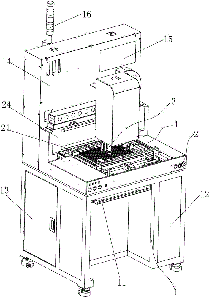
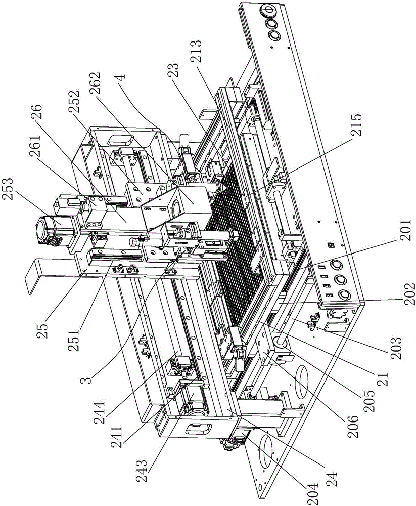
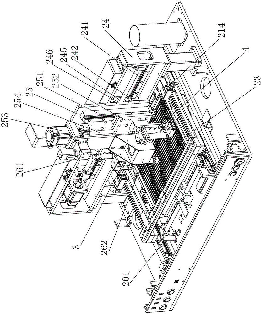
[0034] Such as Figure 1-Figure 4 As shown, what the present invention describes is an automatic desoldering and tin removal equipment. The automatic desoldering and tin removal equipment has a main frame 1, and the main frame 1 is provided with a horizontal workbench 2, wherein:

[0035] A pair of first y-direction rails 201 and corresponding first y-direction sliders 202 are installed on the horizontal workbench 2, and a workpiece is installed between the first y-direction sliders 202 on the two first y-direction rails 201 Fixed jig 21; the first y direction screw mandrel 203 and the first servo motor 204 driving the first y direction screw mandrel 203 are installed on the outside of one of the first y guide rails 201, and the first y direction screw mandrel 203 is provided with There is a matching first screw nut 205 and a first screw nut seat ...


PUM


Abstract

The invention relates to automatic desoldering and detinning equipment. The automatic desoldering and detinning equipment comprises a main frame; the main frame is provided with a horizontal workbench; a workpiece fixing jig and a workpiece preheating table are installed on the horizontal workbench; a portal frame is further erected on the horizontal workbench and provided with an x-direction sliding seat and a z-direction sliding seat; a desoldering assembly and a detinning assembly are installed on the two side edges of the surface of the z-direction sliding seat correspondingly; and a connection plate is further arranged on the outer side of a third servo motor located on a first longitudinal installation plate, a CCD industrial camera is fixed to the upper portion of the connection plate, and the lower portion of the connection is located between the desoldering assembly and the detinning assembly and provided with an LED light source matched with the CCD industrial camera. According to the automatic desoldering and detinning equipment, before being subjected to desoldering and detinning processes, workpieces are all preheated through the workpiece preheating table under the workpieces, the situation that a circuit board is damaged due to the fact that the temperature difference between the upper portion and the lower portion is too large and dilatation coefficients are different can be avoided, the fault rate and scrape rate of the circuit board are substantially decreased, and environment protecting is facilitated.

Description

[0001] Technical field: [0002] The invention relates to the technical field of electronic circuit board rework equipment, in particular to an automatic desoldering and tin removal equipment. [0003] Background technique: [0004] At present, in the circuit board assembly and manufacturing industry, when the device is reworked and soldered, whether it is a BGA pad or a through-hole device pad, it is necessary to remove the residual solder. Due to the current manual operation method, the method of using the electric soldering iron tip to suck the tin strip is used to perform contact desoldering operations on the pads, which will cause the pads to loosen, fall off, and shrink copper. In severe cases, the entire circuit will be damaged. The board is completely scrapped, resulting in huge cost loss, and the subsequent treatment will also cause great pollution to the environment. [0005] Invention content: [0006] The purpose of the present invention is to overcome the shortco...

Claims


Application Information

Patent Timeline
Patent Type & Authority Applications(China)
IPC IPC(8): B23K1/018B23K3/00
CPCB23K1/018B23K3/00
Inventor 杜洪化
Owner 东莞市崴泰电子有限公司
Why Eureka
Try Eureka