Supercharge Your Innovation With Domain-Expert AI Agents!

T-shaped iron core press-in device for motor coil assembling machine

A press-in device and coil set technology, applied in metal processing equipment, metal processing, manufacturing tools, etc., can solve the problems of unguaranteed assembly accuracy, low work efficiency, accuracy dependence, etc., and achieve low cost and volume occupation. Large land area and guaranteed accuracy

Active Publication Date: 2017-05-24
南通凯蒂亚智能设备制造有限公司 +1
View PDF7 Cites 2 Cited by
  • Summary
  • Abstract
  • Description
  • Claims
  • Application Information

AI Technical Summary

Problems solved by technology

[0004] 1. At least two workers are required to cooperate with the operation, which consumes manpower and reduces work efficiency;
[0005] 2. The accuracy of assembly depends on the personal experience of the workers, and the assembly accuracy cannot be guaranteed

Method used


Image

  • T-shaped iron core press-in device for motor coil assembling machine
  • T-shaped iron core press-in device for motor coil assembling machine
  • T-shaped iron core press-in device for motor coil assembling machine

Examples


Embodiment

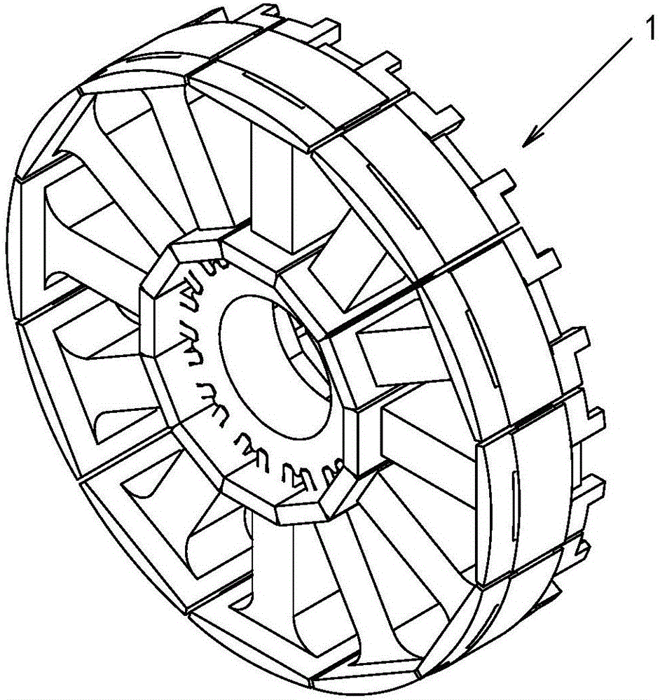
[0031] Example: see Figure 5-15 As shown, a T-shaped iron core pressing device of a motor coil assembly machine:

[0032] see Figure 5 As shown, the motor coil assembly machine includes a frame 2, an annular conveying line 3 is arranged on the frame 2, and a sun-shaped iron core feeding and finished product unloading station 31, a coil unwinding station 31 are successively arranged on the annular conveying line 3 32 and the T-shaped iron core are pressed into the station 3. Conveyor line 3 can adopt double-speed chain.

[0033] see Figure 5 As shown, a plurality of jigs 34 are slidably arranged on the circular conveying line 3 .

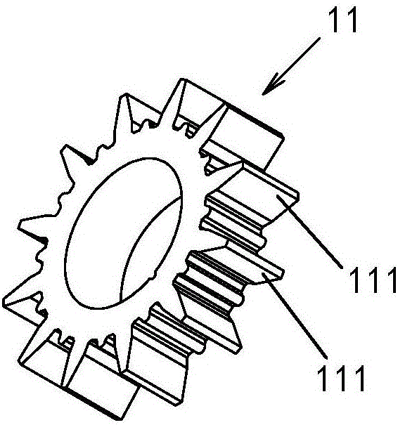
[0034] The specific fixture structure is as Figure 6 As shown, the jig 34 includes a workpiece positioning plate 341. The surface of the workpiece positioning plate 341 is provided with a positioning groove for placing products, and the center of the workpiece positioning plate is vertically provided with a central positioning plate for the ...


PUM


Abstract

A T-shaped iron core press-in device for a motor coil assembling machine is characterized by comprising a progressive rotating disc (71); a workpiece positioning disc (341) is positioned and placed on the progressive rotating disc (71); at least one insertion station (711) and at least one press-in station (712) are arranged on the periphery of the progressive rotating disc (71); the insertion stations (711) are provided with insertion devices (72); the heads of push rods (721) of the insertion devices (72) act towards a T-shaped iron core of a product (1) on the workpiece positioning disc on the progressive rotating disc (71); T-shaped iron core feeding stations (723) are further arranged between the heads of the push rods (721) and the progressive rotating disc (71); the press-in stations (712) are provided with press-in devices (73); and the heads of pressing rods (731) of the press-in devices (73) act towards the T-shaped iron core of the product (1) on the workpiece positioning disc on the progressive rotating disc (71).

Description

technical field [0001] The invention relates to a T-shaped iron core pressing device of a motor coil assembly machine. Background technique [0002] A motor coil 1 such as Figure 1-Figure 4 As shown, it is composed of a sun-shaped iron core 11, twelve T-shaped iron cores 12 and thirteen coils 13, the sun-shaped iron core 11 is located in the middle, and the T-shaped iron core 12 is inserted into the coil 13 and clamped on the on the corner 111 of the sun-shaped iron core 11 . The above-mentioned assembly requirements are relatively high, and there are strict requirements on the outer edge size and the position accuracy of the PIN needle after assembly. [0003] In the prior art, the assembly of the above-mentioned motor coils adopts manual assembly. A worker inserts the T-shaped iron core 12 into the coil 13 and aligns it with the corner 111 of the sun-shaped iron core 11, and then another worker uses the The pressing machine press-fits the T-shaped iron cores 12 in place...

Claims


Application Information

Patent Timeline
Patent Type & Authority Applications(China)
IPC IPC(8): B23P19/04B23P19/00B23P19/10
CPCB23P19/008B23P19/04B23P19/10
Inventor 景建平寇剑波冷亚飞刘广春
Owner 南通凯蒂亚智能设备制造有限公司
Features
  • R&D
  • Intellectual Property
  • Life Sciences
  • Materials
  • Tech Scout
  • Unparalleled Data Quality
  • Higher Quality Content
  • 60% Fewer Hallucinations
Learn More