Rotating table structure with external braking mechanism

A brake mechanism, external technology, applied in the direction of metal processing machinery parts, metal processing equipment, manufacturing tools, etc., can solve the problems of cumbersome maintenance, time-consuming and labor-consuming, poor flexibility, etc., to achieve high-efficiency production that promotes mass production, The effect of eliminating potential safety hazards

Inactive Publication Date: 2017-05-24
GUANGZHOU HAOZHI ELECTROMECHANICAL
View PDF10 Cites 4 Cited by
  • Summary
  • Abstract
  • Description
  • Claims
  • Application Information

AI Technical Summary

Problems solved by technology

[0004] ①The built-in brake mechanism requires certain requirements for product design, parts processing accuracy, assembly methods, and detection methods, and the operation is cumbersome and difficult;
[0005] ②Brake pads are easy to wear parts, which need to be replaced and maintained after reaching the end of their service life. With this structure, the turntable needs to be removed from the machine, then disassembled to replace the spare parts, and then assembled and tested before being put on the machine. This maintenance method is cumbersome and time-consuming. force;
[0006] ③ During the working process of the brake pad, it is inevitable that a small amount of impurities in the worn product will enter the turntable bearing or the inside of the motor after a long time, causing certain safety hazards;
[0007] ④This kind of brake mechanism is finalized after installation, and its flexibility is poor, and some processing methods do not require brake work

Method used


Image

  • Rotating table structure with external braking mechanism
  • Rotating table structure with external braking mechanism
  • Rotating table structure with external braking mechanism

Examples


Embodiment Construction

[0030] The following will clearly and completely describe the technical solutions in the embodiments of the present invention with reference to the accompanying drawings in the embodiments of the present invention. Obviously, the described embodiments are only some, not all, embodiments of the present invention. Based on the embodiments of the present invention, all other embodiments obtained by persons of ordinary skill in the art without making creative efforts belong to the protection scope of the present invention.

[0031] It should be noted that when a component is said to be "fixed" to another component, it can be directly on the other component or there can also be an intervening component. When a component is said to be "connected" to another component, it may be directly connected to the other component or there may be intervening components at the same time. When a component is said to be "set on" another component, it may be set directly on the other component or t...


PUM


Abstract

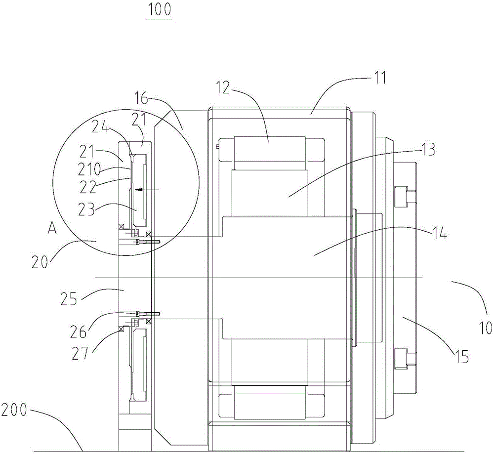
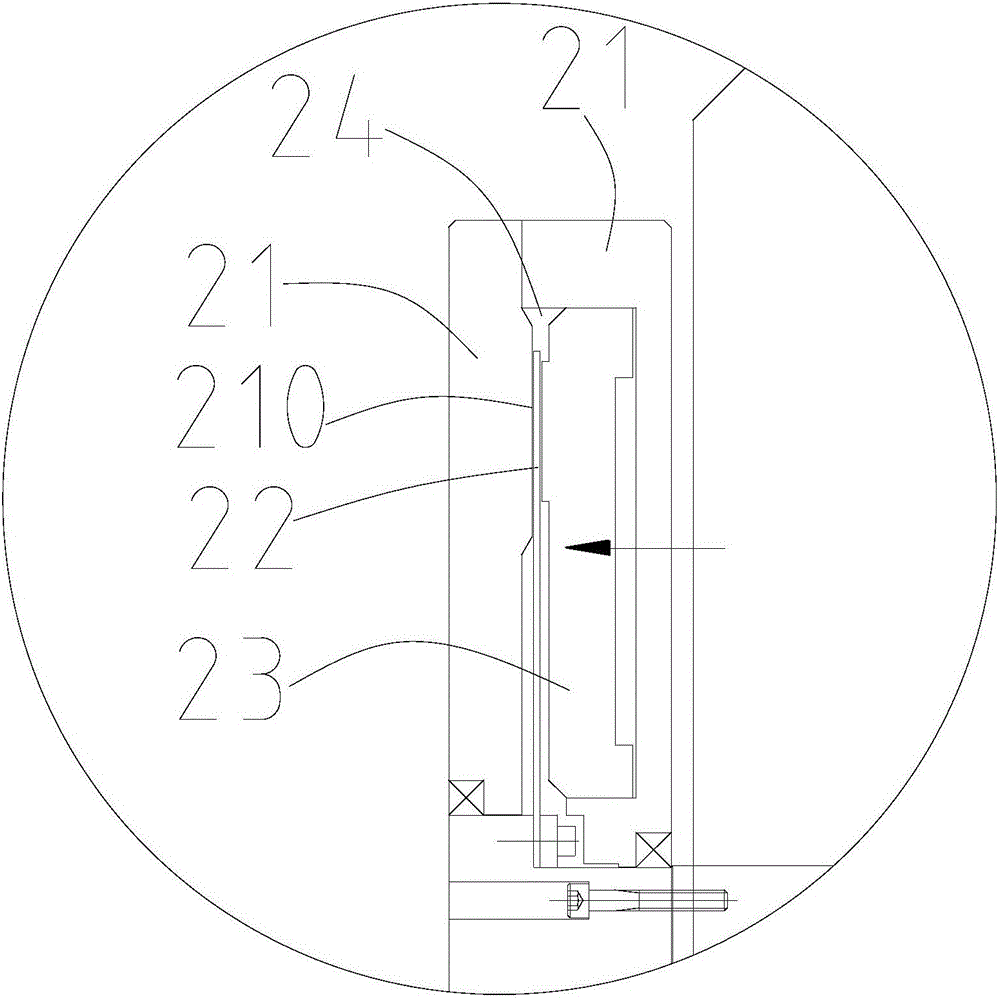
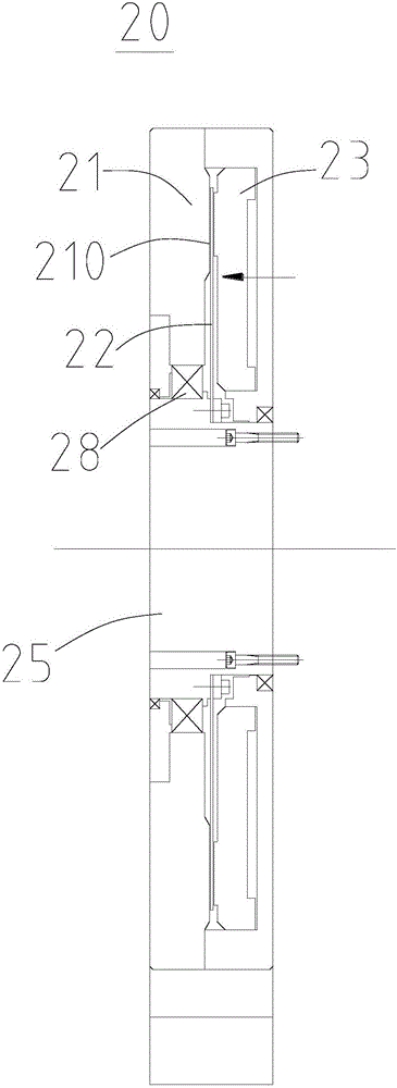
The invention discloses a rotating table structure with an external braking mechanism. The rotating table structure comprises a rotating table and the braking mechanism. The rotating table comprises a main body, a rotary shaft and a rear cover, wherein the main body is fixedly arranged on a workbench, the rotary shaft is rotationally mounted on the main body, the rear cover is fixedly arranged on the main body, and the rotary shaft extends out of the rear cover. The braking mechanism comprises at least one piston, at least one brake pad and at least one friction surface, wherein the at least one brake pad is located between the at least one piston and at least one friction surface, the at least one brake pad is fixedly arranged on the rotary shaft, the at least one friction surface is fixedly arranged on the workbench, and the at least one piston moves in the axial direction of the rotary shaft to enable the at least one brake pad to abut against the at least one friction surface. The braking mechanism is arranged outside the rotating table and is convenient to maintain and replace, potential safety hazards caused by impurities generated by abrasion are eliminated, and braking mechanisms of different structures can be mounted as required.

Description

technical field [0001] The invention relates to the field of machining, in particular to a turntable structure. Background technique [0002] In the machining process, the workpiece is generally clamped on the turntable for turning and other processing. The existing turntable first positions the turntable at the desired position through the control system, and then the brake mechanism ventilates or oil pushes the piston to move axially, and the brake pads connected to the turntable are completely attached to the friction surface. It will generate sufficient braking torque to resist the cutting force and overturning moment generated during work. This mechanical structure braking method can ensure the stability and reliability of the brake without consuming any power. It has been widely used at present. [0003] However, the existing turntable brake mechanism is located inside the turntable structure and has the following defects: [0004] ①The built-in brake mechanism requi...

Claims


Application Information

Patent Timeline
Patent Type & Authority Applications(China)
IPC IPC(8): B23Q1/28
CPCB23Q1/28
Inventor 雷群李军涛汤秀清
Owner GUANGZHOU HAOZHI ELECTROMECHANICAL
Why Eureka
Try Eureka