Outer circle clamper

A gripper and cylinder technology, applied in the field of cylindrical grippers, can solve the problems that affect the clamping accuracy of parts, the overall weight of the chuck, the plane thread error, etc., and achieve high positioning accuracy, simple structure, and reliable fixing. Effect

Active Publication Date: 2017-05-24
浙江宇钻精密元件有限公司
View PDF7 Cites 2 Cited by
  • Summary
  • Abstract
  • Description
  • Claims
  • Application Information

AI Technical Summary

Problems solved by technology

The problem is that for large parts, it is necessary to process flat threads on a larger disc. On the one hand, the flat threads are prone to large errors

Method used


Image

  • Outer circle clamper
  • Outer circle clamper
  • Outer circle clamper

Examples


Embodiment Construction

[0015] In order to make the technical means, creative features, goals and effects achieved by the present invention easy to understand, the present invention will be further described below in conjunction with specific embodiments.

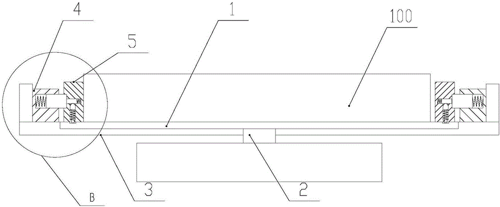
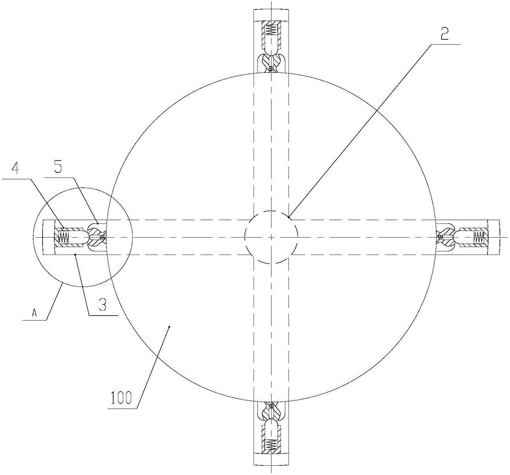
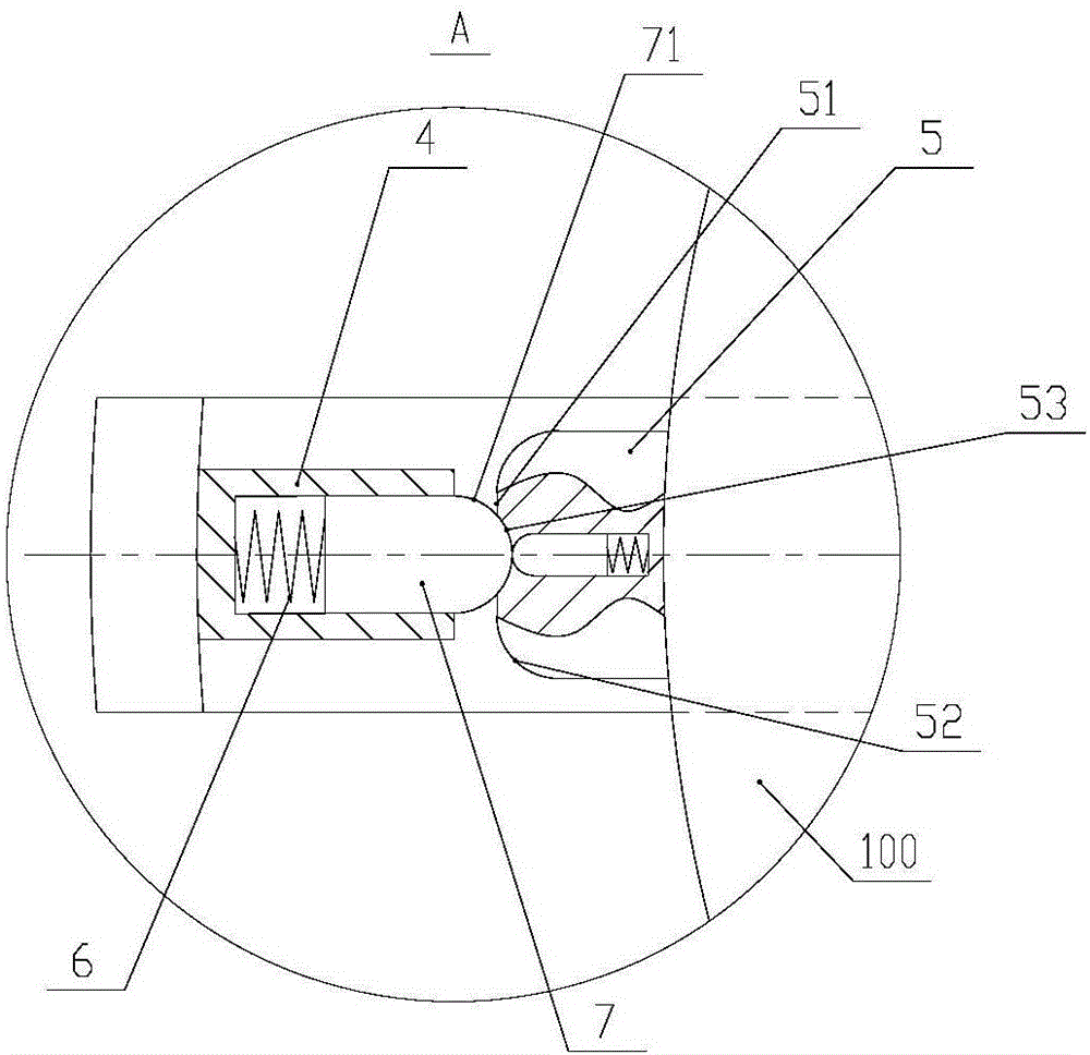
[0016] Please refer to the figure, the present invention provides a technical solution: a cylindrical clamper, including a fixed disc 1, a turntable 2, a support arm 3, a push block 4 and a pressure block 5, the turntable 2 is rotatably arranged on a fixed Below the disk 1, the support arms 3 are at least one pair, and each pair of support arms 3 is symmetrically arranged at both radial ends of the turntable 2 and extends outward from the turntable 2. Same, the push block 4 is fixed above the support arm 3; the pressure block 5 is located within the radial direction of the fixed disk 1 relative to the slide block, and the pressure block 5 can slide radially along the fixed disk 1; when the turntable 2 rotates , the pushing block 4 can press the pr...


PUM


Abstract

The invention discloses an outer circle clamper. The outer circle clamper comprises a fixed plate, a rotating plate, supporting arms, pushing blocks and pressing blocks. The rotating plate is rotationally arranged below the fixed plate. The number of the supporting arms is at least one pair. Each pair of supporting arms are symmetrically arranged at the two ends of the radial direction of the rotating plate and extend to the outside of the rotating plate. The pushing blocks, the pressing blocks and the supporting arms are the same in number. The pushing blocks are fixed above the supporting arms. The pressing blocks are located inside the radial direction of the fixed plate relative to sliding blocks and can slide in the radial direction of the fixed plate. When the rotating plate rotates, the pushing blocks can extrude the pressing blocks to move towards the interior of the fixed plate and abut against the outer circle of a machined part on the fixed plate in a pressing mode. According to the outer circle clamper, the machined part is clamped through the pushing blocks on the supporting arms and the pressing blocks on the fixed plate; compared with a three-jaw or four-jaw chuck, the outer circle clamper is simple in structure and light in equipment weight; and especially for large-size machined parts, the outer circle clamper is high in positioning precision.

Description

technical field [0001] The invention relates to an outer circle holder. Background technique [0002] The parts with outer circular contours are usually clamped by three-jaw and four-jaw chucks when they are processed. The structure of the three-jaw chuck is to process plane threads on the disc, and the claws cooperate with the plane threads. By rotating the disc, the The flat nut drives the lower claw to clamp the outer circle of the part. The problem is that for large parts, it is necessary to process flat threads on a larger disc. On the one hand, the flat threads are prone to large errors, which will affect the clamping accuracy of the parts. On the other hand, the overall weight of the chuck is relatively large. , high manufacturing cost. Contents of the invention [0003] Aiming at the deficiencies in the prior art, the technical problem to be solved by the present invention is to provide an outer circular clamper, which can improve the clamping accuracy and reduce...

Claims


Application Information

Patent Timeline
IPC IPC(8): B23Q3/00
CPCB23Q3/00B23Q2703/10
Inventor 石宪云
Owner 浙江宇钻精密元件有限公司
Why Eureka
Try Eureka