
High-pressure grinding material air jet grinding material flow control device and control method thereof

A flow control device and gas jet technology, which is applied in the direction of abrasive feeding device, used abrasive processing device, abrasive, etc., can solve the problem of continuous and stable feeding, uncontrollable abrasive flow, and unsmooth feeding To achieve the effect of convenient and feasible working method, controllable abrasive flow rate and continuous supply

Pending Publication Date: 2017-05-24
HENAN POLYTECHNIC UNIV
View PDF6 Cites 8 Cited by
  • Summary
  • Abstract
  • Description
  • Claims
  • Application Information

AI Technical Summary

Problems solved by technology

These feeding methods often have unsmooth feeding, easy to block, cannot achieve continuous and stable feeding, and the abrasive flow rate is uncontrollable, and under high pressure conditions, the abrasive with a large mesh size will harden in the abrasive tank, resulting in Less or no abrasive

Method used


Image

  • High-pressure grinding material air jet grinding material flow control device and control method thereof
  • High-pressure grinding material air jet grinding material flow control device and control method thereof

Examples


Embodiment 1

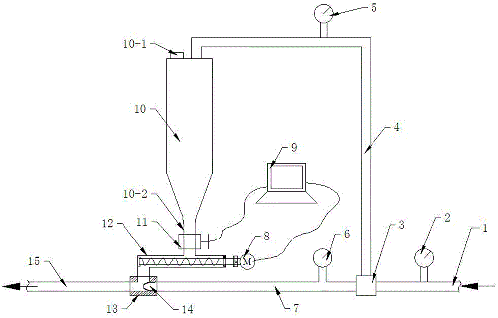
[0021] Embodiment one, such as figure 1 , a high-pressure abrasive gas jet abrasive flow control device, comprising an air inlet pipe 1 and an abrasive tank 10, the right end of the air inlet pipe 1 is connected to a high-pressure air source, and the air inlet pipe 1 is connected to a pressure gauge 2 close to the high-pressure air source and The high-pressure control valve 6 located at the left end of the intake pipe 1, the left side of the high-pressure control valve 6 is connected with the high-pressure air pipe 7 whose left end is the injection nozzle 14, and the outer surface of the injection nozzle 14 is provided with threads and connected to the jet tee The right port of 13 is screwed, and the abrasive pot 10 is a hollow structure with a cylindrical upper end and a conical lower end. The upper end of the abrasive pot 10 is sealed and provided with a feeding port 10-1 connected to the atmosphere. The lower end of 10 is a feed opening 10-2 that is sealed and connected wit...

Embodiment 2

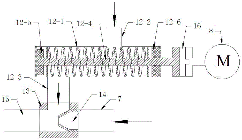
[0022] Embodiment two, such as Figure 1-2 , is basically the same as the first embodiment, the difference is that the screw conveying device 12 includes a conveying cylinder 12-1 and a screw 12-4 located in the conveying cylinder 12-1, and the conveying cylinder 12-1 is provided with a A square abrasive inlet 12-2 and an abrasive outlet 12-3 located at the lower left, the inside of the delivery cylinder 12-1 is provided with a support 12-5 located at the left end and a gasket 12-6 located at the right end, the screw The left end of 12-4 is hinged on the support 12-5, and the right end of the screw rod 12-4 passes through the sealing gasket 12-6 and the right wall of the delivery cylinder 12-1 and is connected with the drive motor 8 through the coupling 16, The abrasive inlet 12 - 2 is in sealing connection with the lower end of the abrasive tank 10 , and the abrasive outlet 12 - 3 is in sealing connection with the upper port of the jet tee 13 .

Embodiment 3

[0023] Embodiment three, such as Figure 1-2 , which is basically the same as Embodiment 1 or Embodiment 2, except that the inlet pipe 1 is connected with a diverter tee 3 between the pressure gauge 2 and the high-pressure control valve 6, and the left port of the diverter tee 3 and the right port are all sealed with the intake pipe 1, the upper port of the split tee 3 is sealed with one end of the balance air pipe 4, the middle of the balance air pipe 4 is connected with a low pressure control valve 5, and the other end of the balance air pipe 4 One end is sealingly connected with the upper end of the abrasive pot 10, and the opening of the feeding port 10-1 is sealed.


PUM


Abstract

The invention discloses a high-pressure grinding material air jet grinding material flow control device and a control method thereof. The device comprises an air inlet pipe and a grinding material tank. The right end of the air inlet pipe is connected with a high-pressure air source; the air inlet pipe is connected with a high-pressure control valve; a high-pressure air pipe with the left end provided with an ejecting spray nozzle is connected to the left side of the high-pressure control valve; the ejecting spray nozzle is in screw joint with a right end opening of a jet flow tee joint; the upper end of the grinding material tank is sealed and provided with a charging opening communicating with the atmosphere; the lower end of the grinding material tank is in sealed connection with a screw conveying device; a blanking switch is disposed in the connection position between the grinding material tank and the screw conveying device; the screw conveying device is connected with a driving motor; the lower portion of the screw conveying device is in sealed connection with an upper end opening of the jet flow tee joint; the right end opening, at the lower end of the screw conveying device, of the jet flow tee joint is connected with the ejecting spray nozzle; and air flow can form a negative pressure zone at the upper end of the ejecting spray nozzle so as to avoid the situation that the air flow reversely flows to the screw conveying device and consequently falling off of a grinding material is blocked. The high-pressure grinding material air jet grinding material flow control device is simple in structure and a working method is convenient to implement and feasible.

Description

technical field [0001] The invention relates to the technical field of abrasive jets, in particular to a high-pressure abrasive gas jet abrasive flow control device and a control method thereof. Background technique [0002] Abrasive gas jet is a new processing technology, which accelerates the abrasive through high-pressure air, and the jet impacts the target body. It has been widely used in the fields of drilling, cutting and deburring. The abrasive can obtain higher speed and high processing efficiency; in the abrasive air jet, as long as the air flow can reach, it can be processed by jet, and the abrasive gas jet can process parts that cannot be processed by traditional technology. Compared with abrasive waterjet, abrasive waterjet uses water as the medium, and its jet processing operation consumes a lot of energy. At the same time, abrasive waterjet operation produces a large amount of waste water, which is not easy to treat, making the working environment poor. The ab...

Claims


Application Information

Patent Timeline
Patent Type & Authority Applications(China)
IPC IPC(8): B24C7/00B24C9/00
CPCB24C7/0053B24C7/0092B24C9/00
Inventor 刘勇魏建平李志强刘笑天徐向宇
Owner HENAN POLYTECHNIC UNIV
Learn More