
Upper portion flange supporting mechanism used for ethylene cracking furnace decoking

A technology of ethylene cracking furnace and supporting mechanism, which is applied in cracking, non-catalytic thermal cracking, petroleum industry, etc., can solve problems such as bending and sinking displacement furnace tubes, and achieve the advantages of avoiding bending, prolonging service life, convenient operation and labor saving Effect

Active Publication Date: 2017-05-24
SINOPEC YANGZI PETROCHEM +1
View PDF4 Cites 0 Cited by
  • Summary
  • Abstract
  • Description
  • Claims
  • Application Information

AI Technical Summary

Problems solved by technology

[0006] The purpose of the present invention is to provide an upper flange support mechanism for coke cleaning in ethylene cracking furnaces, which solves the problem in the prior art that the second-pass furnace tubes sink and shift due to loss of support during coke cleaning in ethylene cracking furnaces and cause the furnace tubes to bend question

Method used


Image

  • Upper portion flange supporting mechanism used for ethylene cracking furnace decoking
  • Upper portion flange supporting mechanism used for ethylene cracking furnace decoking
  • Upper portion flange supporting mechanism used for ethylene cracking furnace decoking

Examples


Embodiment 1

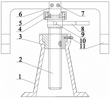
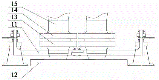
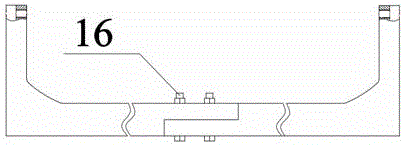
[0026] Such as figure 1 , 2 As shown, an upper flange support mechanism for coke cleaning of an ethylene cracking furnace includes two lifting bodies, and the lifting bodies include a base 1 , a nut 3 , a screw 2 , a holder cup 6 , a thrust bearing 4 and a moving arm 11 . The base 1 is provided with a cavity, the nut 3 is fixed on the top of the cavity of the base 1, the lower part of the screw rod 2 is inserted in the cavity of the base 1, and is connected with the nut 3 by threads, and the upper diameter of the screw rod 2 is A handle jack 9 is opened in the direction, and a handle 8 is inserted into the handle jack 9, and the handle 8 is located above the base. By applying a thrust to the handle 8, a bending moment is generated to make the screw 2 rotate relative to the base 1. The screw rod 2 is movably connected with the support cup 6 through the thrust bearing 4, the thrust bearing 4 is arranged above the screw rod 2, the fixed ring of the thrust bearing 2 is fixedly co...

Embodiment 2

[0029] In order to ensure that the whole device is more stable during the working process, the lifting body also includes a limit sleeve 5 , which is sleeved on the outside of the thrust bearing 4 and screwed to the top of the screw rod 2 . The screw rod 2 and the holder cup 6 are further fixed by the limit sleeve 5, which well limits the horizontal and vertical displacement of the holder cup 6 relative to the screw rod 2, and ensures that the whole device is more stable during the working process.

[0030] In order to ensure that the nut 3 is relatively fixed to the base 1, the top of the inner wall of the base 1 is a stepped structure, the outer wall of the nut 3 is a stepped structure, and the step on the top of the inner wall of the base 1 is matched with the step of the outer wall of the nut 3, and the base 1 and the outer wall of the nut 3 are matched. Correspondingly, the nut 3 is provided with a threaded hole, and the base 1 and the nut 3 are fixedly connected by the sc...


PUM


Abstract

The invention discloses an upper portion flange supporting mechanism used for ethylene cracking furnace decoking. The upper portion flange supporting mechanism comprises two uplifting main bodies, and every uplifting main body comprises a pedestal, a nut, a screw, a holder cup, a thrust bearing and a movement arm. The pedestal is provided with a cavity, the nut is fixed at the top of the cavity of the pedestal, the lower portion of the screw is inserted to the cavity of the pedestal and is in threaded connection with the nut, a handle jack is arranged in the screw along a radial direction, and a handle is inserted to the handle jack. The screw is movably connected with the holder cup through the thrust bearing, and a clamping slot penetrates through the upper end of the holder cup along a radial direction. The middle portion of the movement arm is clamped in the clamping slot in the upper end of the holder cup to guarantee fixed connection between the movement arm and the holder cup. The screw is rotated to lift the movement arm in the decoking process in order to support a lower portion, so furnace tube bending caused by sinking displacement of the lower flange due to gravity is prevented, and the service life of the furnace tube is prolonged.

Description

technical field [0001] The invention belongs to the technical field of chemical machinery, and in particular relates to an upper flange support mechanism for cleaning coke in an ethylene cracking furnace. Background technique [0002] For ethylene cracking furnaces, the bending deformation of the furnace tube is the most common problem. According to statistics, during the operation of the Lummus SRT cracking furnace, 80% of the failure of the furnace tube in the radiant section comes from the bending deformation of the furnace tube. When the furnace tubes are bent and deformed, the same group of furnace tubes will be close together or deflected to the furnace wall, which will seriously affect the heat transfer effect of the radiant furnace tubes and the safe, stable and long-term operation of the cracking furnace. [0003] The ethylene cracking furnace of the prior art is equipped with a traditional quenching waste pot at the outlet of the furnace top. The lower head flang...

Claims


Application Information

Patent Timeline
IPC IPC(8): C10G9/16
Inventor 胡天生史永红王元华
Owner SINOPEC YANGZI PETROCHEM
Learn More