Cutting machine head and cutting machine

A cutting machine and machine head technology, applied in the field of cutting machines, can solve the problems of inability to cut, expensive production and assembly costs, affecting the cutting efficiency of the cutting machine, etc., and achieve the effect of improving cutting efficiency and reducing sharpness.

Inactive Publication Date: 2017-05-24
长园和鹰科技(河南)有限公司
View PDF6 Cites 2 Cited by
  • Summary
  • Abstract
  • Description
  • Claims
  • Application Information

AI Technical Summary

Problems solved by technology

Among them, the working mode of the vibrating knife is to drive the vibrating knife head to reciprocate continuously up and down through a transmission mechanism such as a motor, so as to realize the cutting of the knife head on the material, but because the structure of the vibrating knife is very complicated, its production and assembly costs are too high Expensive, especially in order to realize the high-frequency reciprocating motion of the cutter head, the cost of the transmission mechanism of the motor drive machine is even more expensive
The working method of the circular knife is through the friction between the knife and the material when the machine head is walking, so that the circular knife is passively rotated to realize ...

Method used


Image

  • Cutting machine head and cutting machine
  • Cutting machine head and cutting machine
  • Cutting machine head and cutting machine

Examples


Embodiment Construction

[0027] In order to make the object, technical solution and advantages of the present invention clearer, various embodiments of the present invention will be described in detail below in conjunction with the accompanying drawings. However, those of ordinary skill in the art can understand that, in each implementation manner of the present invention, many technical details are provided for readers to better understand the present application. However, even without these technical details and various changes and modifications based on the following implementation modes, the technical solution claimed in each claim of the present application can be realized.

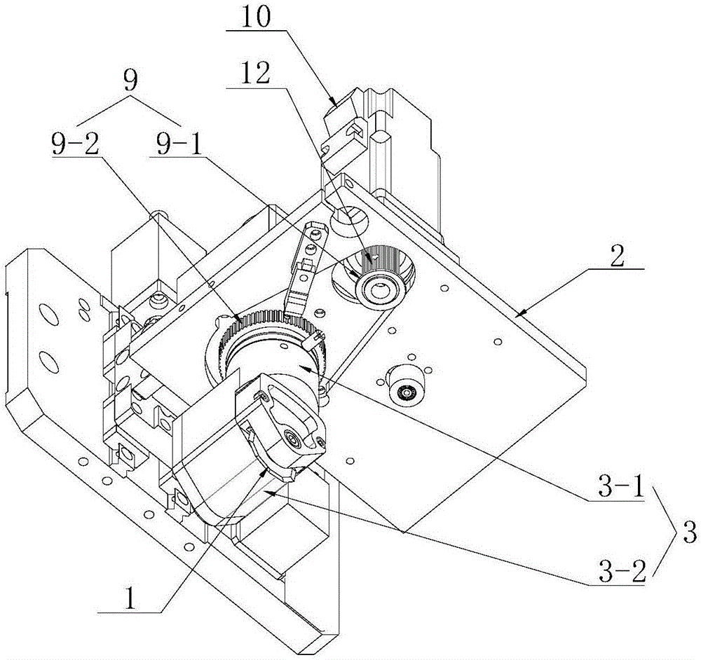
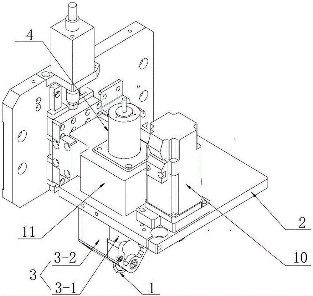
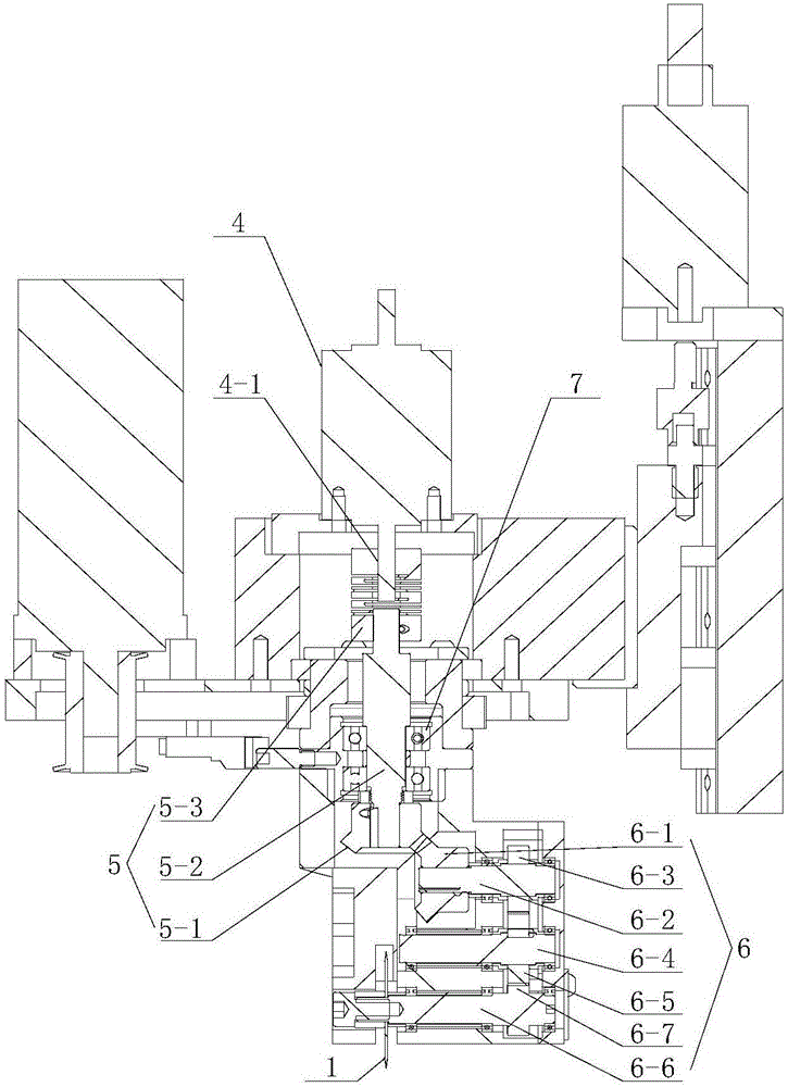
[0028] A first embodiment of the present invention relates to a cutting machine head mounted on a frame of the cutting machine. And as figure 1 , figure 2 and image 3 As shown, the machine head includes a cutting knife mechanism, a machine head mounting plate for installing the cutting knife mechanism, and a lifting mec...


PUM


Abstract

The invention relates to a cutting machine head which is installed on a walking rack of a cutting machine. The cutting machine head comprises a cutter mechanism, a machine head installing plate used for installing the cutter mechanism and a lifting mechanism used for driving the machine head installing plate to conduct vertical movement in a manner of being perpendicular to a tabletop of the cutting machine; the cutter mechanism comprises a circular cutter and a cutter handle which is rotatably arranged on the machine head installing plate, and the cutter handle is used for being connected with the circular cutter; and the cutter mechanism further comprises a first driving device used for driving the circular cutter to rotate and a second driving device used for driving the cutter handle to rotate. Compared with the prior art, when the cutter mechanism is used for cutting leather materials, the circular cutter can be driven by the driving device to rotate, and therefore cutting of the leather materials is achieved; the second driving device controls the cutter handle to rotate and controls cutting angles of the circular cutter to the leather materials, therefore, the circular cutter can cut the leather materials in an active rotary manner, it is guaranteed that the leather materials can be completely cut in the cutting process, and the cutting efficiency of the cutting machine to the leather materials can be greatly improved.

Description

technical field [0001] The invention relates to a cutting machine, in particular to a cutting mechanism of the cutting machine and a cutting machine with the cutting mechanism. Background technique [0002] At present, in some leather cutting, cloth cutting and other industries, materials are often cut according to the needs of production, and modern people have higher and higher requirements for cutting technology, and high-speed efficiency is also required while pursuing high-quality cutting. For example, cutting out different shapes, different angles, and different lengths of cloth or leather requires manual cutting by workers in many cases. It is difficult to guarantee the quality of cutting, and the efficiency is relatively low. Therefore, in order to overcome this defect, the cutting machine was born And born. [0003] As a precision instrument for cutting materials such as cloth and leather, the cutting machine has been widely used in some leather and cloth industrie...

Claims


Application Information

Patent Timeline
IPC IPC(8): C14B15/10D06H7/00D06H1/00
CPCC14B15/10C14B2700/113D06H1/00D06H7/00
Inventor 尹智勇
Owner 长园和鹰科技(河南)有限公司
Why Eureka
Try Eureka