
Connection structure of frame steel beams and composite floor slab

A technology for superimposing floor slabs and connecting structures, which is applied to slabs, building components, building structures, etc., can solve problems such as increasing manpower, material resources, and financial resources, difficulty in making and installing steel columns, and increasing construction costs. Flexibility, high machining accuracy, and the effect of reducing steel consumption

Inactive Publication Date: 2017-05-24
CHINA 22MCC GROUP CORP +1
View PDF5 Cites 2 Cited by
  • Summary
  • Abstract
  • Description
  • Claims
  • Application Information

AI Technical Summary

Problems solved by technology

The connection between the steel frame column and the concrete beam requires a corbel plate with connecting overlapping steel bars, a connecting sleeve, and a hole for passing through the steel bar on the web plate of the steel frame column. The variety of tendons brings certain difficulties to the fabrication and installation of steel columns.
[0005] The practice of the existing technology increases the amount of steel used in the prefabricated house. During the construction process, there are many types of studs and shear keys, and the steel bars of the concrete structure. The quality requirements in the installation are relatively high. Failure to complete each construction step will affect From the progress of the next process, the phenomenon of mutual restriction often occurs, which will lead to a long construction period, virtually increase manpower, material resources, and financial resources, and lead to an increase in construction costs

Method used


Image

  • Connection structure of frame steel beams and composite floor slab
  • Connection structure of frame steel beams and composite floor slab
  • Connection structure of frame steel beams and composite floor slab

Examples


Embodiment Construction

[0026] The present invention is described in detail below with reference to accompanying drawing and embodiment:

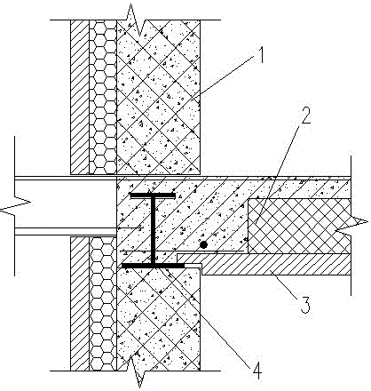
[0027] attached Figure 1-3 It can be seen that a connection structure between a frame steel beam and a laminated floor includes a connection structure between a middle frame steel beam and a laminated floor and a connection structure between a side frame steel beam and a laminated floor, and is characterized in that:

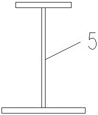
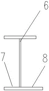
[0028] The upper and lower flange plates of the middle frame steel beam are parallel to each other; the width of the lower flange plate of the middle frame steel beam is 25-30mm wider than the edge of the upper flange plate of the middle frame steel beam;

[0029] The upper and lower flanges of the side frame steel beams are parallel to each other;

[0030] The outer sides of the upper and lower flange panels of the side frame steel beams are flush; to facilitate the installation of exterior wall panels;

[0031] The width of the lower flange pla...


PUM


Abstract

The invention relates to a connection structure of frame steel beams and a composite floor slab. The connection structure comprises a connection structure of a middle frame steel beam and the composite floor slab and a connection structure of an edge frame steel beam and the composite floor slab, and the width of the lower flange plate of the middle frame steel beam is larger than those of the plate edges of an upper flange plate of the middle frame steel beam respectively by 25-30 mm; the outdoor sides of the upper flange plate and the lower flange plate of the edge frame steel beam are abreast; the width of the lower flange plate, on one side close to the indoor, of the edge frame steel beam is larger than that of the plate edge of the upper flange plate of the edge frame steel beam. According to the connection structure of the frame steel beams and the composite floor slab, steel secondary beams are reduced, the project cost is saved, the working efficiency is improved, and the construction quality is improved.

Description

technical field [0001] The invention relates to a building construction component, in particular to a connection structure between frame steel beams and laminated floor slabs. Background technique [0002] With my country's "energy saving and emission reduction" policy, housing is the focus, especially prefabricated steel structure housing brings a lot of room for development. Among many residential buildings, prefabricated steel structure housing is most suitable for factory production. The design will be , Production, construction and installation are integrated, changing the traditional "on-site construction" to "factory manufacturing". The prefabricated steel structure house has light weight, low cost, simple installation, fast construction speed, less environmental pollution during construction, good seismic performance, recyclable, economical and environmental protection, etc., which meet the requirements of the "green building" put forward by the country. [0003] The...

Claims


Application Information

Patent Timeline
IPC IPC(8): E04B5/29
CPCE04B5/29
Inventor 李素强谢辉莫绍杰
Owner CHINA 22MCC GROUP CORP
Learn More