

Tower crane transportation concrete spreading device
A distributing device and concrete technology, applied in the field of pouring concrete, can solve problems affecting concrete pouring and the like
Active Publication Date: 2017-05-24
平邑经济开发区投资发展有限公司
View PDF7 Cites 2 Cited by
- Summary
- Abstract
- Description
- Claims
- Application Information
AI Technical Summary
Problems solved by technology
[0002] At present, in the field of construction engineering, the concrete distribution equipment for high-rise buildings is installed on the cast-in-place concrete floor formwork, which not only affects the concrete pouring, but also requires frequent installation and removal of the distribution equipment.
Method used
View moreImage
Smart ImageViewing Examples

Examples
Embodiment Construction
[0008] SUMMARY OF THE INVENTION The specific implementation manners of the present invention have been described in detail and will not be repeated here.
Login to View More PUM
 Abstract
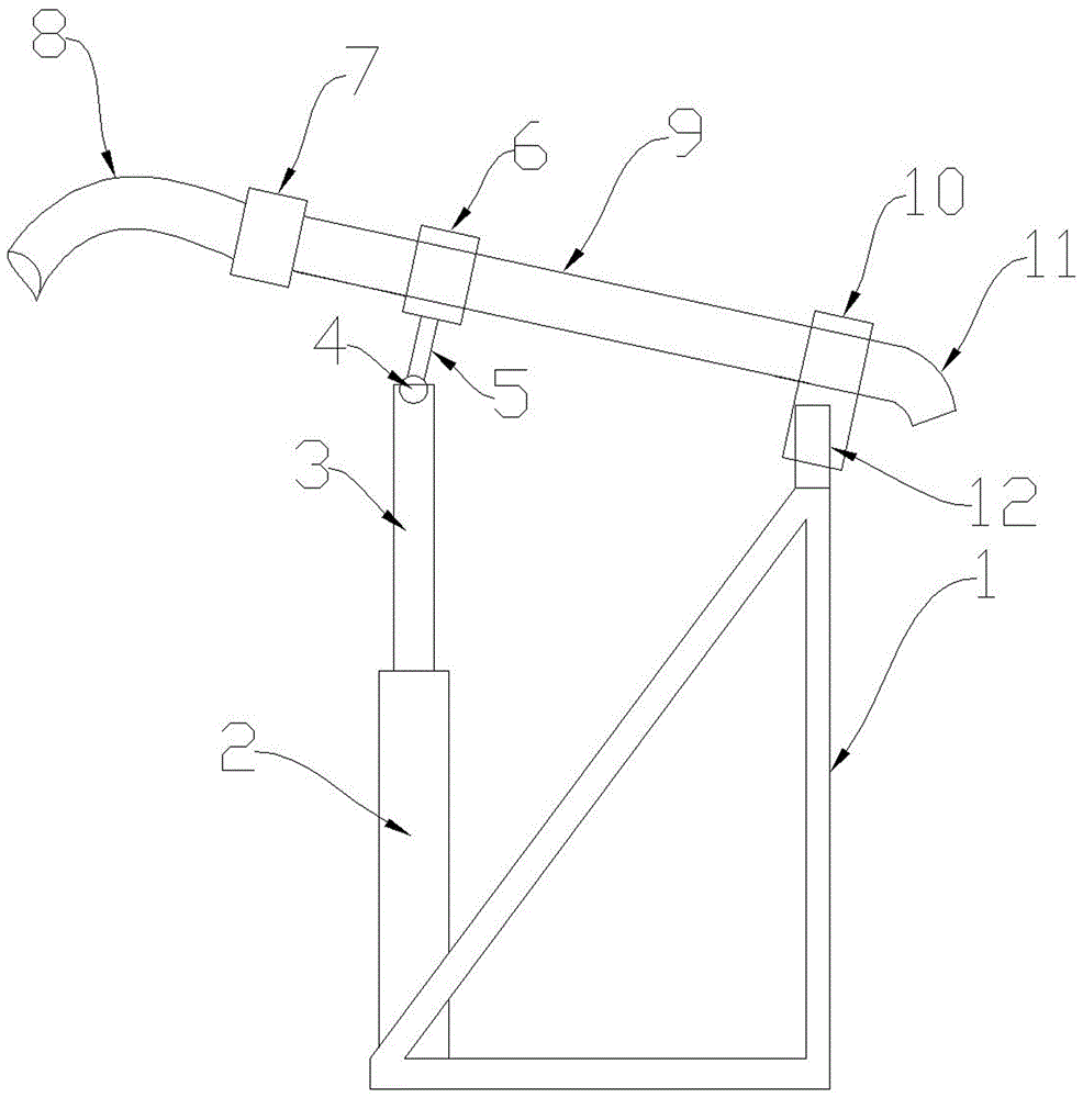
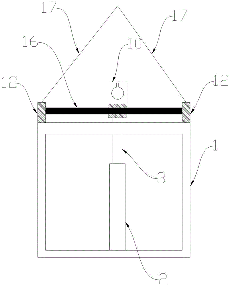
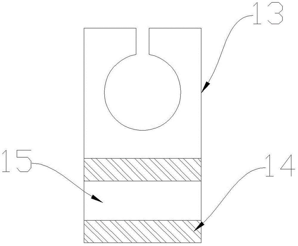
The invention relates to a tower crane transportation concrete spreading device. The tower crane transportation concrete spreading device is mainly applied to concrete pouring of the field of constructional engineering. By means of a tower crane, the tower crane transportation concrete spreading device does not need to be mounted and dismounted frequently. Meanwhile, the tower crane transportation concrete spreading device is simple in structure, low in cost and convenient to operate. The tower crane transportation concrete spreading device is mainly composed of a triangular support rack, a hydraulic cylinder, a piston and a translation device. According to the operating principle of the tower crane transportation concrete spreading device, the tower crane hoists the concrete spreading device to a pouring spot, then a concrete conveying pump is started, and concrete flows out of an elbow through a hose and a rigid pipe; when the vertical pouring angle of concrete needs to be changed, the piston can be extended or shortened to push the left portion of the rigid pipe to move up or down, and then the elbow can swing up and down to change the vertical pouring angle of the concrete; when the horizontal pouring position of the concrete needs to be changed, the translation device can be pushed left and right, so that the elbow can slide left and right to change the horizontal pouring position of the concrete.
Description
technical field [0001] The invention is mainly used for pouring concrete in the field of construction engineering. Background technique [0002] At present, in the field of construction engineering, the concrete distribution equipment for high-rise buildings is installed on the cast-in-place concrete floor formwork, which not only affects the concrete pouring, but also requires frequent installation and removal of the distribution equipment. Contents of the invention [0003] The present invention solves the above-mentioned problems. It utilizes a tower crane to move and transport the material distribution device without frequent installation and removal of the material distribution device, and the material distribution device is simple in structure, low in cost and easy to operate; the present invention mainly consists of a triangular support frame (1), a hydraulic cylinder ( 2), piston (3), universal ball (4), rod (5), tube clip (6), union (7), hose (8), hard tube (9), t...
Claims
Login to View More Application Information
Patent Timeline
 Patent Type & AuthorityApplications(China)
IPC IPC(8): E04G21/04
CPCE04G21/0427
Inventor彭宝安
Owner平邑经济开发区投资发展有限公司