Laminated restrictor

A laminate restrictor and wall plate technology, which is applied in the lubrication of turbine/propulsion device, engine components, and engine lubrication, etc., can solve the problem of inability to separate oil and gas, and achieve great use value, simple overall structure, and overall weight. light effect

Inactive Publication Date: 2017-05-24
CHINA GAS TURBINE ESTAB
View PDF8 Cites 0 Cited by
  • Summary
  • Abstract
  • Description
  • Claims
  • Application Information

AI Technical Summary

Problems solved by technology

Existing throttling devices are all simple structures of different forms, which can realize the throttling function and cannot separate oil and gas

Method used


Image

  • Laminated restrictor
  • Laminated restrictor
  • Laminated restrictor

Examples


Embodiment approach 1

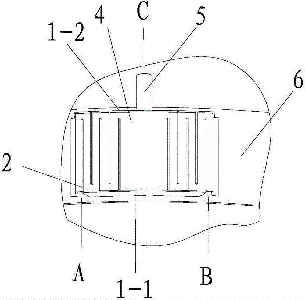
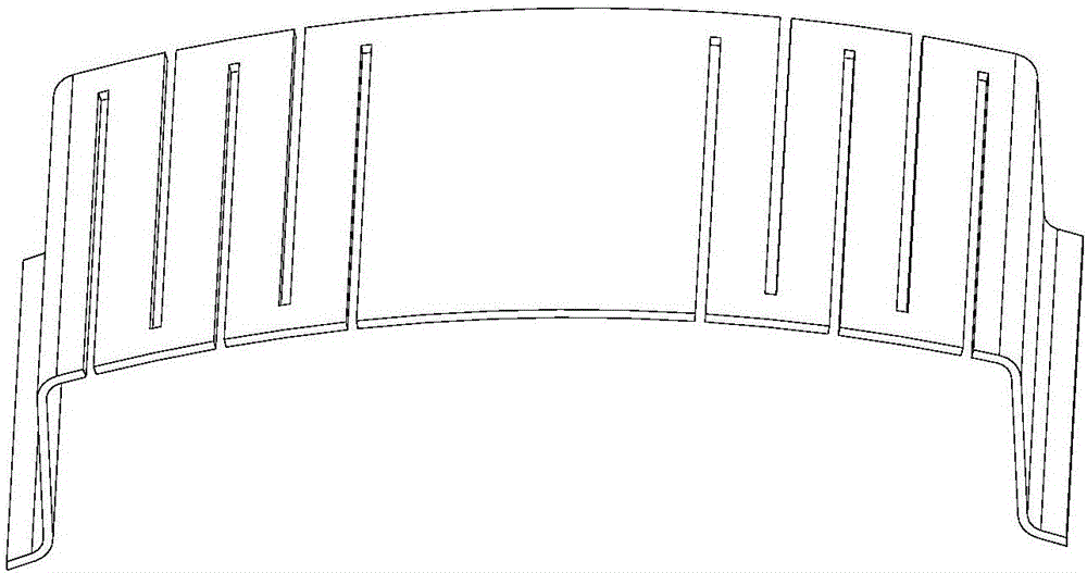
[0019] see figure 1 , image 3 , which is a structural schematic diagram of Embodiment 1 of the floor restrictor of the present invention. In this embodiment, the laminate restrictor is a plate structure, integrated inside the lubricating oil tank cavity, which consists of a front baffle 1-1, an oil retention plate 2, a rear baffle 1-2, a wall plate 4, Ventilation pipe 5 and bottom plate 6 are formed. Wherein, the ventilation pipe 5 is processed from a pipe material, and is fixed at the outlet of the laminate restrictor by welding; The inlet position of the side air inlet A and the right air inlet B has an oil throwing hole, which is located between the front baffle 1-1 and the bottom plate 6; the rear baffle 1-2 is a plate structure, and the installation On the rear end surface of the wall plate 4, there are two oil throwing holes located between the rear baffle plate 1-2 and the bottom plate 6; the bottom plate 6 is located inside the cavity of the integrated lubricating ...

Embodiment approach 2

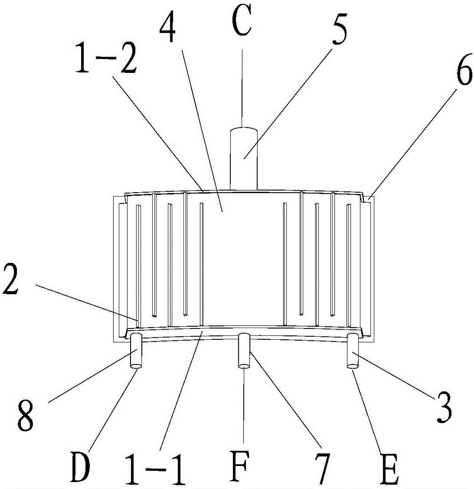
[0022] see figure 2 , image 3 , which is a structural schematic diagram of Embodiment 2 of the floor restrictor of the present invention. In this embodiment, the laminate restrictor is a plate structure, designed as a separate lubricating oil accessory, which consists of a front baffle 1-1, a rear baffle 1-2, an oil retaining plate 2, and a right air inlet Pipe 3 wall plate 4, ventilation pipe 5, bottom plate 6 oil outlet pipe 7 and left side air inlet pipe 8 are formed. Wherein, the ventilation pipe 5 is processed from a pipe material, and is fixed on the outlet of the laminate restrictor by welding; The inlet position of the left air inlet pipe 8 and the right air inlet pipe 3; the rear baffle 1-2 is a plate structure, installed on the rear end surface of the wall plate 4; the bottom plate 6 is located in a thin plate structure, located on the wall The bottom of the plate 4; the oil retaining plate 2 is a rectangular plate structure; the wall plate 4 is processed from a...


PUM


Abstract

The invention discloses a laminated restrictor. The laminated restrictor comprises baffle plates (1), oil retaining plates (2), a wall plate (4), a vent pipe (5) and a box inner wall (6). According to the laminated restrictor, the integral structure is simple, manufacturability is good, and cost is relatively low; the laminated restrictor can be properly improved according to different requirements of a ventilating system on the laminated restrictor; and the laminated restrictor can be independently utilized and arranged in a vent pipeline, and can be integrated in other lubricating oil accessories like a lubricating oil tank, so that the laminated restrictor is quite wide in application range and has relatively high utilization value.

Description

technical field [0001] The invention relates to a throttling device, in particular to a layered throttling device used in the ventilation sub-system of the lubricating system of a small aviation gas turbine engine. Background technique [0002] In the aviation gas turbine engine lubrication system, the size of the ventilation flow is an important factor affecting the oil consumption. If the ventilation flow is large, the oil consumption will be greater. Therefore, from the perspective of reducing the oil consumption, the Methods of reducing ventilation flow. Although the existing centrifugal ventilator can separate the oil mist in the ventilation air, the best centrifugal ventilator can only separate the oil droplets larger than 2-3μm, and the ventilation flow still contains a certain amount of unseparated tiny oil droplets. In order to reduce lubricating oil consumption, appropriate measures should be taken in the design of the lubrication system to reduce the ventilation...

Claims


Application Information

Patent Timeline
Patent Type & Authority Applications(China)
IPC IPC(8): F02C7/06
CPCF02C7/06
Inventor 景国庆宋飞李贵林陈亮李炎军刘涛
Owner CHINA GAS TURBINE ESTAB
Why Eureka
Try Eureka