
Vehicle and intake air temperature management controller, system and method

A technology for managing the controller and intake air temperature, which is applied in the field of vehicle intake temperature management, vehicle intake air temperature adjustment, controller and management system, and can solve the problems of insufficient combustion, engine reliability and service life vehicle maintenance burden, Improve fuel consumption and other issues, achieve the effect of improving reliability and service life, reducing vehicle maintenance costs, and avoiding insufficient combustion

Active Publication Date: 2017-05-24
BEIQI FOTON MOTOR CO LTD
View PDF14 Cites 8 Cited by
  • Summary
  • Abstract
  • Description
  • Claims
  • Application Information

AI Technical Summary

Problems solved by technology

However, the working environment, especially for trucks, is often harsh
For example, in cold weather and high altitude areas, when the ambient temperature is low, the intake air temperature of the engine is too low, which will lead to poor mixing and atomization of fuel and air, and insufficient combustion, which will make the engine horsepower unable to perform normally and fuel consumption will increase significantly
And it is often started in low temperature air, which will cause carbon deposits in the engine
In addition, in hot weather and when the ambient temperature in tropical areas is high, the intake air temperature of the engine is too high and the air density is reduced, which will also cause insufficient combustion and other consequences.
And if the high temperature in the engine cylinder continues, it will cause engine failure
Therefore, whether the intake air temperature is too high or too low will affect the engine operation, life and reliability
The resulting engine reliability and service life issues also impose a burden on vehicle maintenance

Method used


Image

  • Vehicle and intake air temperature management controller, system and method
  • Vehicle and intake air temperature management controller, system and method
  • Vehicle and intake air temperature management controller, system and method

Examples


Embodiment Construction

[0058] Specific embodiments of the present invention will be described in detail below in conjunction with the accompanying drawings. It should be understood that the specific embodiments described here are only used to illustrate and explain the present invention, and are not intended to limit the present invention.

[0059] In the present invention, in the case of no contrary description, the used orientation words such as "up and down" are defined when the vehicle air inlet provided by the present invention is in normal operation. Specifically, reference may be made to figure 1 direction of the drawing. "Front and rear" are defined based on the flow direction of the corresponding gas, specifically, the gas flows from front to back.

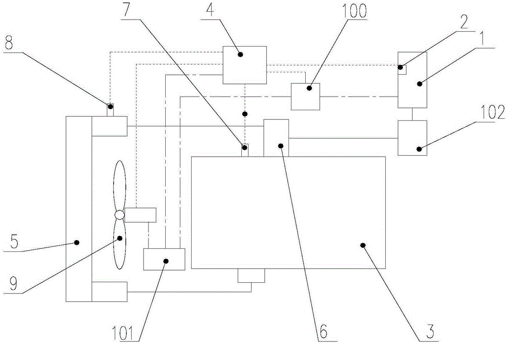
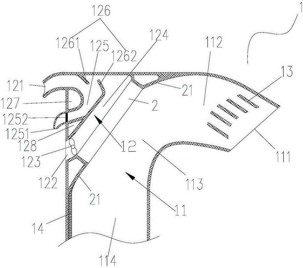
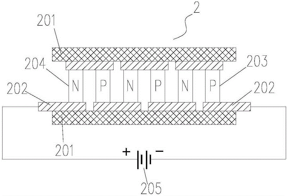
[0060] Such as Figure 1 to Figure 3 As shown, in order to achieve the purpose of the present invention, the present invention provides a technology for controlling the temperature of the intake air of the vehicle, which includes the improvem...


PUM


Abstract

The invention discloses a vehicle and intake air temperature management controller, system and method. According to the method, whether intake air of a vehicle is heated or cooled is judged according to the intake air temperature of an engine in combination with the intake air temperature of an intercooler. According to the vehicle and intake air temperature management controller, system and method, the Peltier effect is innovatively used, in cooperation with a temperature management device, the electronics principle is used, and the controllable temperature management system is provided; the intake air temperature is controlled through the intelligent logic, and the intake air system performance is improved greatly; the problems of insufficient combustion, carbon deposition of the engine, increase of the fuel consumption and the like caused by the too high or too low intake air temperature are solved, the operating reliability of the engine is improved, and the service life of the engine is prolonged; meanwhile, the vehicle maintenance cost brought by the similar problems is lowered; and the problems, needed to be solved in the prior art, of vehicles, especially the truck industry are solved.

Description

technical field [0001] The invention relates to the field of temperature regulation of vehicle intake air, in particular to a vehicle intake air temperature management method, a controller and a management system applying the method, and a vehicle using the system. Background technique [0002] At present, for example, the engine of a vehicle requires air to enter the engine to participate in combustion and work, which requires the air to be at a suitable temperature. For example, for a truck that uses a diesel engine as a power source, the air enters from the intake port, is compressed by the turbocharger, and the temperature rises, and then enters the engine after being cooled by the intercooler. However, the working environment in which trucks in particular operate is often harsh. For example, in cold weather and high-altitude areas, when the ambient temperature is low, the intake air temperature of the engine is too low, which will cause poor mixing and atomization of f...

Claims


Application Information

Patent Timeline
Patent Type & Authority Applications(China)
IPC IPC(8): F02D45/00F02M31/02F02B29/04
CPCY02T10/12
Inventor 刘金波林梅友刘福萍苏朝霞
Owner BEIQI FOTON MOTOR CO LTD
Learn More