Clamp for tensile strength test of material

A technique for tensile strength and testing, which is applied in the field of fixtures for holding specimens, and can solve the problems of unavoidable failure of the tensile test at the end of the specimen, unsatisfactory axial tension of the specimen, and extrusion failure of the end. , to increase the tensile test success rate, increase the test success rate, and achieve the effect of axial tensile failure

Pending Publication Date: 2017-05-24
HUNAN UNIV OF SCI & TECH
View PDF3 Cites 11 Cited by
  • Summary
  • Abstract
  • Description
  • Claims
  • Application Information

AI Technical Summary

Problems solved by technology

During the tensile strength test, if the material specimen is directly clamped on the material testing machine, due to the characteristics of some materials, it will be found that the end of the specimen is prone to local extrusion damage during the test. The failure of the end leads to the undesired axial tensile failure of the specimen and the failure of the test
In order to prevent partial pressure damage at the end of the test piece, a reinforcement sheet is pasted on the clamping section of the tensile test piece, but this will also cause abnormal effects such as weak bonding, peeling of the clamping section, and local extrusion damage.
In response to these situations, researchers have designed many fixtures. The common point of these fixtures is that the loading of tensile force is based on the friction force on the surface of the specimen, which is not essentially different from being directly clamped on the material testing machine, or it cannot avoid the end of the specimen. Tensile test failure due to head problems

Method used


Image

  • Clamp for tensile strength test of material
  • Clamp for tensile strength test of material
  • Clamp for tensile strength test of material

Examples


Embodiment Construction

[0022] The present invention will be further described in detail below in conjunction with the accompanying drawings and embodiments.

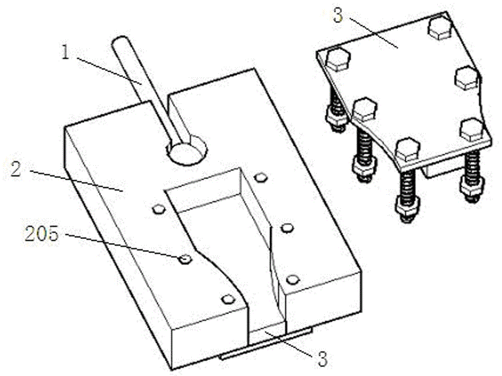
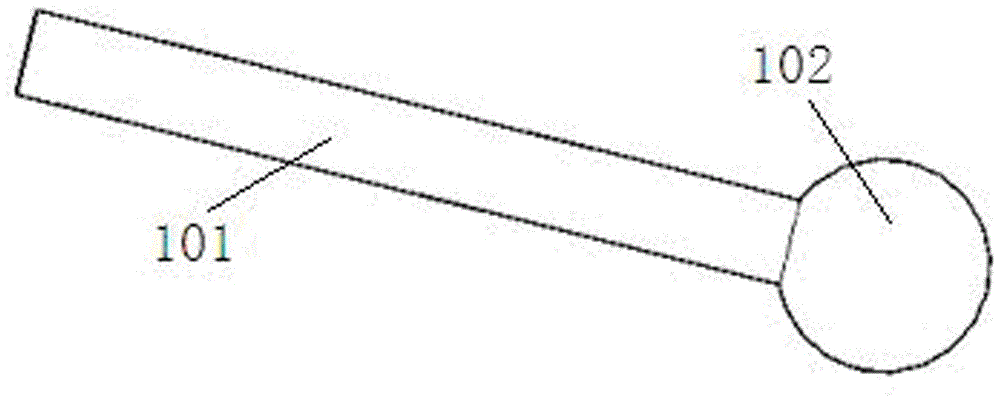
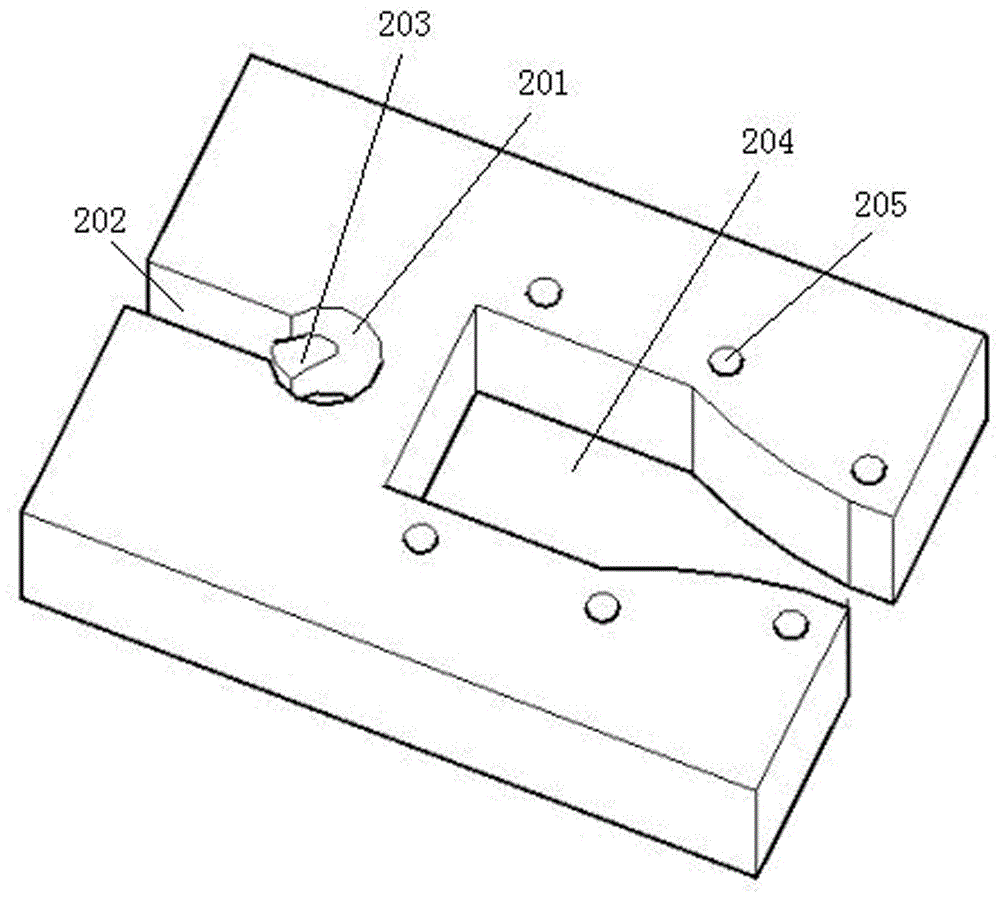
[0023] see figure 1 , This embodiment includes a pull rod 1 , a chuck 2 and a pressing device 3 . see figure 2 , the tie rod 1 includes a circular rod 101 , one end of the rod 101 is connected to the test device, and the other end of the rod 101 is affixed to a spherical end 102 . see image 3 , chuck 2 is a block component, from image 3 It can be seen from the figure that one side of the chuck 2 is provided with an open slot matching the shape of the pull rod 1, the open slot includes a cylindrical slot 201 with a diameter slightly larger than that of the spherical end 102, and the cylindrical slot 201 communicates with a bar-shaped open slot 202 , the width of the strip-shaped opening groove 202 is slightly larger than the diameter of the rod 101; a spherical groove 203 for fixing the spherical end 102 is provided at the middle positio...


PUM


Abstract

The invention discloses a clamp for tensile strength test of a material. The clamp disclosed by the invention comprises a pull rod, a chuck and compressing devices. The pull rod comprises a rod piece, one end of which is connected to a testing device while the other end of which is fixedly connected to a spherical end; the chuck is a bulk member, wherein an open slot which accords with the pull rod in shape is formed in one side of the chuck, and the spherical end can be embedded into the open slot and can drive the rod member to rotate in a small range; an open slot hole which accords with the end part of a test piece in shape is formed in the other side of the chuck, the end part of the test piece is placed in the middle of the open slot hole, and the compressing devices are placed on the upper and lower surfaces and compress the test piece by fastening compression bolts penetrating through bolt holes in the compressing devices and in the open slot hole edge. The clamp disclosed by the invention is simple in structure, convenient to use, high in effectiveness and low in cost, can increase the success rate of the tensile test to a great extent, and is convenient to popularize and use.

Description

technical field [0001] The invention belongs to a test device, in particular to a clamp used for clamping a test piece during a material tensile strength test. Background technique [0002] In the field of combined structures and new materials, material performance tests are often involved, and material performance tests include tensile strength tests of materials. During the tensile strength test, if the material specimen is directly clamped on the material testing machine, due to the characteristics of some materials, it will be found that the end of the specimen is prone to local extrusion damage during the test. The failure of the end leads to the undesired axial tensile failure of the specimen, which leads to the failure of the test. In order to prevent partial pressure failure at the end of the specimen, a reinforcing sheet is attached to the clamping section of the tensile specimen, but this will also cause abnormal effects such as weak bonding, peeling of the clampi...

Claims


Application Information

Patent Timeline
IPC IPC(8): G01N3/04
CPCG01N3/04G01N2203/0017G01N2203/0423
Inventor 黄海林李遨言兴刘光伟曾垂军祝明桥
Owner HUNAN UNIV OF SCI & TECH
Why Eureka
Try Eureka