

Automatic correction method, device and system of sampling signal
An automatic correction and sampling signal technology, which is applied in the general control system, control/regulation system, program control, etc., can solve the problem of low accuracy of sampling data, and achieve the effect of improving efficiency and high accuracy
- Summary
- Abstract
- Description
- Claims
- Application Information
AI Technical Summary
Problems solved by technology
Method used
Image

Examples
Embodiment 1
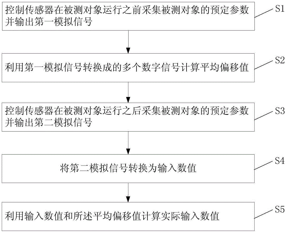
[0026] Combine below figure 1 and figure 2 Describe in detail a sampling signal automatic correction method provided by the embodiment of the present invention, which can be executed by the above-mentioned controller 13, such as figure 2 The method shown includes the following steps:
[0027] S1, control the sensor 11 to collect predetermined parameters of the measured object 10 and output a zero-point analog signal (the first analog signal) before the measured object 10 runs, and at this time, the controller 13, the sensor 11, and the analog-to-digital converter 12 are energized and run, and are controlled. The test object 10 is not powered on. At this time, due to the influence of factors such as electromagnetic interference, the zero-point analog signal (the first analog signal) is usually not 0.
[0028]S2, convert the zero-point analog signal (the first analog signal) into the zero-point digital signal (the first digital signal), the zero-point analog signal (the firs...
Embodiment 2
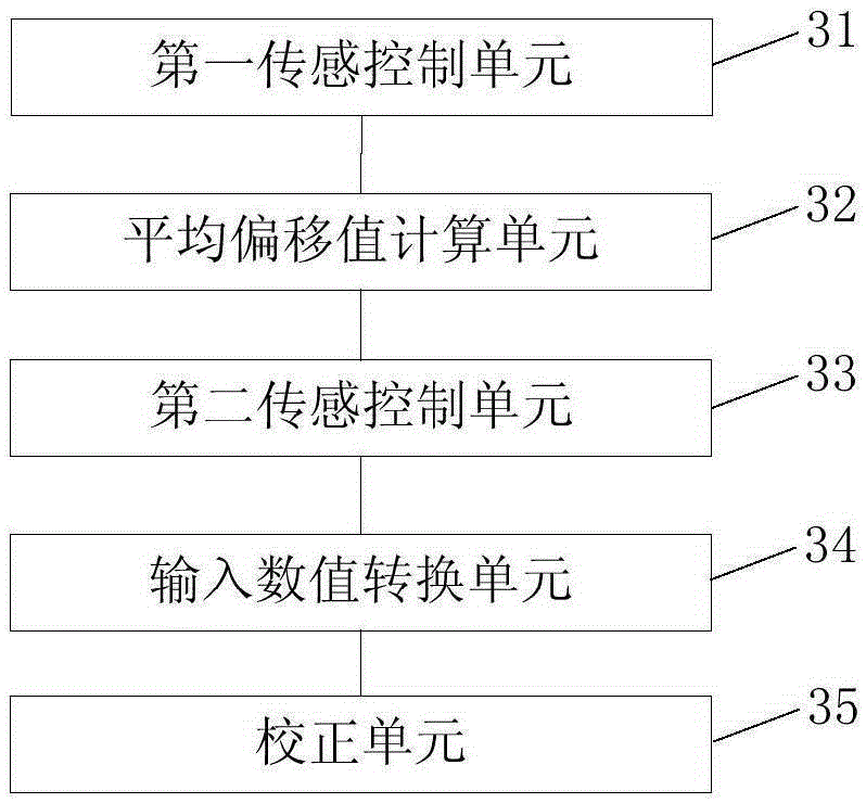
[0044] The following will combine figure 1 and image 3 A detailed description of a sampling signal automatic correction device provided by an embodiment of the present invention, the device includes:
[0045] The first sensing control unit 31 is configured to control the sensor 11 to collect predetermined parameters of the measured object before the measured object 10 runs and output a first analog signal;
[0046] An average offset value calculation unit 32, configured to calculate an average offset value by using a plurality of digital signals converted from the first analog signal;
[0047] The second sensing control unit 33 is configured to control the sensor 11 to collect predetermined parameters of the measured object and output a second analog signal after the measured object 10 runs;
[0048] an input value conversion unit 34, configured to convert the second analog signal into an input value;
[0049] A correction unit 35, configured to calculate an actual input v...
Embodiment 3
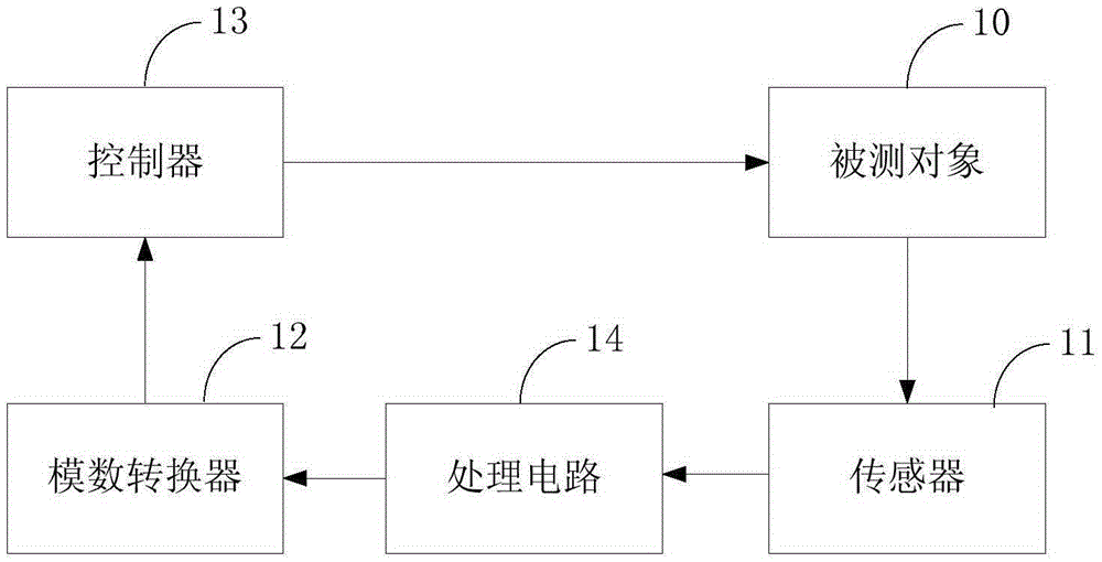
[0061] An embodiment of the present invention provides an automatic correction system for sampling signals, such as figure 1 The system shown includes:
[0062] An automatic correction system for sampling signals, characterized in that it includes:
[0063] The sensor 11 is used to collect the output signal of the measured object;
[0064] The controller 13 is configured to perform the following steps:
[0065] Controlling the sensor 11 to collect predetermined parameters of the measured object before the measured object 10 runs and outputting a first analog signal;
[0066] calculating an average offset value by using a plurality of digital signals converted from the first analog signal;
[0067] controlling the sensor to collect predetermined parameters of the measured object and output a second analog signal after the measured object 10 runs;
[0068] converting the second analog signal to an input value;
[0069] An actual input value is calculated using the input val...
PUM
 Abstract
Description
Claims
Application Information