High-pressure-difference gas target device suitable for superhigh-intensity deuterium tritium fusion neutron source

A technology of fusion neutron and target device, which is applied in the direction of neutron source, etc., can solve the problems of melt-through, excessive heat flux density of target point, and massive release of tritium from neutron source damage, so as to reduce the cost of use and avoid the problem of heat bearing. Effect

Inactive Publication Date: 2017-05-24
HEFEI INSTITUTES OF PHYSICAL SCIENCE - CHINESE ACAD OF SCI
View PDF5 Cites 8 Cited by
  • Summary
  • Abstract
  • Description
  • Claims
  • Application Information

AI Technical Summary

Problems solved by technology

But for a neutron yield of 10 14 -10 16 n / s ultra-high-current deuterium-tritium fusion neutron source, if you continue to use solid-state tritium targets, a large amount of energy of the high-current ion beam will be deposited in a very small area on the tritium target, causing the heat flux density of the target to exceed per square centimeter hundreds of kilowatts
If the target cannot be effectively cooled and dissipated, the temperature of the target will rise sharply, and the target will be melted within milliseconds, resulting in serious accidents such as damage to the neutron source and a large release of tritium

Method used


Image

  • High-pressure-difference gas target device suitable for superhigh-intensity deuterium tritium fusion neutron source
  • High-pressure-difference gas target device suitable for superhigh-intensity deuterium tritium fusion neutron source
  • High-pressure-difference gas target device suitable for superhigh-intensity deuterium tritium fusion neutron source

Examples


Embodiment Construction

[0034] It should be noted that the embodiments in the application and the features in the embodiments can be combined with each other if there is no conflict. Hereinafter, the present invention will be described in detail with reference to the drawings and in conjunction with the embodiments.

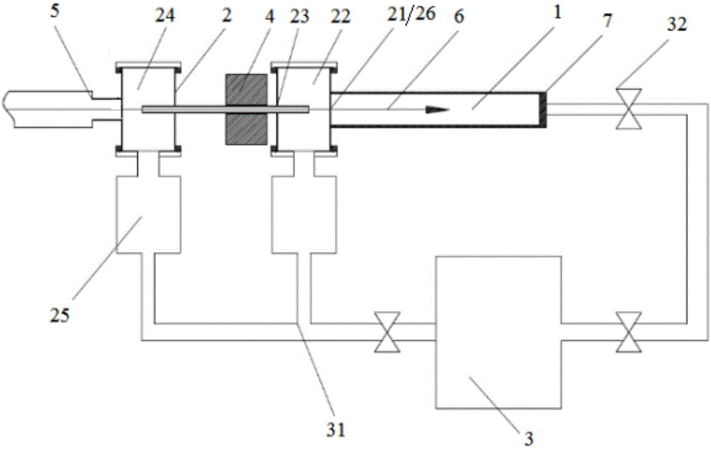
[0035] The invention can be used at the end of a strong current deuterium-tritium fusion neutron source to generate a strong current fusion neutron. The tritium gas or deuterium gas in the reaction gas chamber and the accelerator deuterium beam undergo fusion reaction. A major design feature of the structure of this device is that while achieving high-current and intense beam transmission, the end of the accelerator is realized through a vacuum differential system. -5 Pa to gaseous target reaction gas chamber 10 3 A total of 8 orders of pressure spanning of Pa, long-distance and low-loss transmission of high-strength deuterium beams in small-diameter pipes, and on-line purification, recove...


PUM


Abstract

The invention discloses a high-pressure-difference gas target device suitable for a superhigh-intensity deuterium tritium fusion neutron source. The high-pressure-difference gas target device comprises an accelerator interface and a reaction gas cavity. The device also comprises a vacuum difference system, a beam constraint device and a reaction gas cycle collection device, wherein the vacuum difference system comprises a second-stage difference chamber, a first-stage difference chamber, a small-bore long pipeline and a small-bore flange; the beam constraint device is used for carrying out focusing on a deuterium beam in the small-bore long pipeline to enable beam envelope to be smaller than the inner diameter of the small-bore long pipeline and the small-bore flange; and the reaction gas cycle collection device is connected with the first-stage difference chamber and the second-stage difference chamber through a vacuum pump and is used for carrying out separation and purification on the gas discharged by the vacuum pump and then, enabling the gas to enter the reaction gas cavity through a throttle valve. The deuterium beam output from the accelerator interface passes through the vacuum difference system and realizes pressure jump from 10<-5>Pa at the tail end of the accelerator to 10<-3>Pa of the reaction gas cavity, and then, has fusion reaction with a tritium gas or a deuterium gas in the reaction gas cavity to generate high-energy fusion neutrons, and the tritium gas or the deuterium gas is subjected to online purification, collection and recycling.

Description

Technical field [0001] The invention relates to a high-pressure-difference gaseous target device suitable for an ultra-high-current strong deuterium-tritium fusion neutron source, and is mainly used for neutron generation of a strong-current deuterium-tritium fusion neutron source. Background technique [0002] The deuterium-tritium fusion neutron source uses a high-current deuterium ion beam to bombard a tritium target to produce a deuterium-tritium fusion reaction to produce 14MeV high-energy fusion neutrons, which can be used in research fields such as neutron physics, medical physics, radiation protection and nuclear technology applications. It is an advanced nuclear energy An essential scientific device for research and application of nuclear technology. [0003] Currently 10 countries in the world 11 -10 13 The n / s high-current deuterium-tritium fusion neutron source uses a high-speed rotating solid tritium target system, that is, tritium is adsorbed on high thermal conductiv...

Claims


Application Information

Patent Timeline
Patent Type & Authority Applications(China)
IPC IPC(8): G21G4/02
CPCG21G4/02
Inventor 吴宜灿王文季翔王永峰刘超
Owner HEFEI INSTITUTES OF PHYSICAL SCIENCE - CHINESE ACAD OF SCI
Why Eureka
Try Eureka