
Optimized power allocation method applied to parallel operation of grid-connected converters

A distribution method and power optimization technology, applied in the direction of single-network parallel feeding arrangement, etc., can solve the problems of electric energy waste, increase system loss, poor output external characteristics, etc., to improve system efficiency, simple control method, and low system cost. Effect

Active Publication Date: 2017-05-24
HEFEI UNIV OF TECH
View PDF1 Cites 13 Cited by
  • Summary
  • Abstract
  • Description
  • Claims
  • Application Information

AI Technical Summary

Problems solved by technology

Power droop control is the main control method for parallel connection of converters. It realizes parallel connection of converters with different capacities, and distributes output power according to its own rated capacity according to load changes. However, due to poor output characteristics, it is not suitable for direct grid connection.
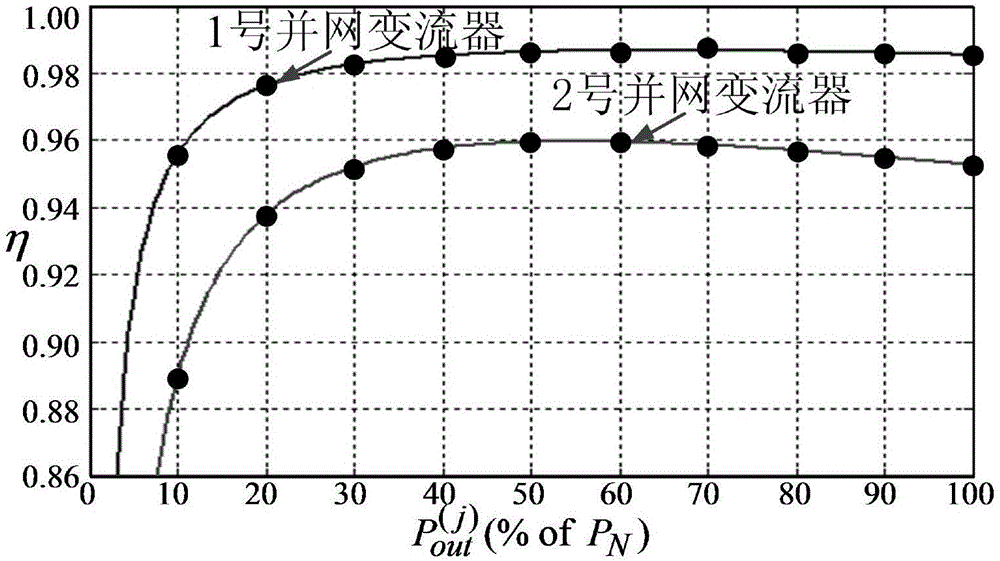
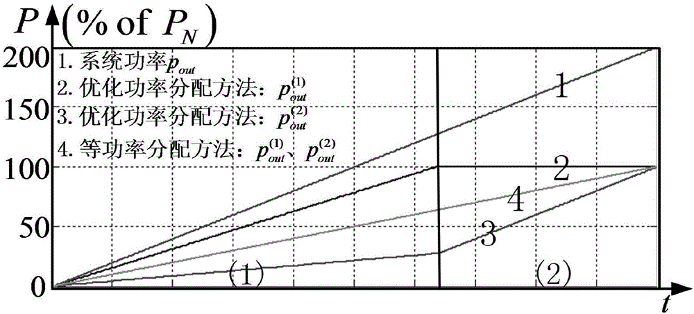
In addition, the power droop control does not take into account the energy conversion efficiency of each converter unit itself, but only uses the capacity ratio of the converter as the only basis for power distribution, which makes the parallel system unable to operate at the point of maximum system efficiency , increasing the loss of the system, resulting in a great waste of electric energy
[0003] On the other hand, it is very difficult to improve the efficiency of converters of the kilowatt level and above
In order to improve the efficiency of parallel systems, more efficient topologies are often used, such as replacing the two-level structure with a three-level structure, and using thicker wires when winding the inductor. These methods will directly lead to an increase in system cost and control complexity , its effect is only to increase the efficiency by 0.5-1%

Method used


Image

  • Optimized power allocation method applied to parallel operation of grid-connected converters
  • Optimized power allocation method applied to parallel operation of grid-connected converters
  • Optimized power allocation method applied to parallel operation of grid-connected converters

Examples


Embodiment Construction

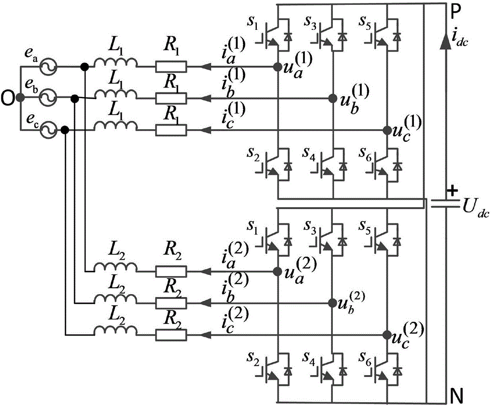
[0038] Such as figure 1 As shown, this embodiment takes two grid-connected converters as an example for illustration, and the provided optimized power distribution method applied to the parallel operation of grid-connected converters is carried out as follows:

[0039] Step 1. Collect the input voltage, input current, output voltage and output current of n grid-connected converters when they are running independently, and calculate the input power and output power of the corresponding grid-connected converters;

[0040] Step 2. Based on the power loss characteristics of the grid-connected converter, the efficiency model of a single grid-connected converter is established and the coefficients of each sub-term are determined;

[0041] Among them, the efficiency model based on power loss of No. j grid-connected converter is:

[0042]

[0043] In the formula (1), j is the label of the grid-connected converter, indicating the j-number grid-connected converter, 1≤j≤n; n j Res...


PUM


Abstract

The invention discloses an optimized power allocation method applied to parallel operation of grid-connected converters. The input power and output power of each grid-connected converter in independent operation are detected, and the item coefficients of an efficiency model based on the load characteristics of the converter are determined based on the input power and the output power. A system efficiency expression of n grid-connected converters during parallel operation is built according to the efficiency model of each grid-connected converter. By calculating the output power of each grid-connected converter, optimized output power allocation is carried out in order to improve the system efficiency of a parallel system under the condition that grid-connected converters with different energy conversion efficiency are in parallel operation. Therefore, optimized control during parallel operation of grid-connected converters such as grid-connected inverters and PWM rectifiers is realized.

Description

technical field [0001] The invention relates to the field of parallel operation of grid-connected converters, and more specifically relates to an optimized power distribution method applied to parallel operation of grid-connected converters. Background technique [0002] With the rapid development of industry and the gradual increase of electrical equipment, the requirements for the capacity, efficiency and reliability of converters are getting higher and higher. The independent operation of a single converter unit can no longer meet the demand, and the parallel operation of converters has become An important way to expand system capacity. Power droop control is the main control method for parallel connection of converters. It realizes parallel connection of converters with different capacities, and distributes output power according to its own rated capacity according to load changes. However, due to poor output characteristics, it is not suitable for direct grid connection...

Claims


Application Information

Patent Timeline
Patent Type & Authority Applications(China)
IPC IPC(8): H02J3/46
CPCH02J3/46
Inventor 姜卫东皋艳廖玉茗丁星星马炜程
Owner HEFEI UNIV OF TECH
Learn More