Power equipment box with fireproofing and cooling functions

A technology of electrical equipment box and function, applied in the direction of electrical equipment structural parts, electrical equipment shell/cabinet/drawer, electrical components, etc., can solve the problems of non-circulating air, fire, lack of maintenance, etc., to achieve good sealing effect, fire control effect

Inactive Publication Date: 2017-05-24
泉州市知产茂业工业设计有限公司
View PDF0 Cites 11 Cited by
  • Summary
  • Abstract
  • Description
  • Claims
  • Application Information

AI Technical Summary

Problems solved by technology

The air in the traditional power equipment box does not circulate, the heat cannot be discharged in time or the heat is concentrated and accumulated in one electrical equipment, and the cooling efficiency of only opening cooling holes on the power equipment box is low
The power equipment box is usually installed outdoors or under the eaves of a single household. During the peak period of electricity consumption, the electrical load in the power equipment box is relatively high. At this time, the electrical equipment generates a large amount of heat. In addition, most of the electrical equipment in the electrical equipment box has been used for more than a year and lacks maintenance. The electrical equipment has poor contact under continuous use and is prone to short circuits, which can cause fires. Therefore, a power equipment with fire-proof and heat-dissipating functions is proposed box

Method used


Image

  • Power equipment box with fireproofing and cooling functions
  • Power equipment box with fireproofing and cooling functions
  • Power equipment box with fireproofing and cooling functions

Examples


Embodiment Construction

[0014] The following will clearly and completely describe the technical solutions in the embodiments of the present invention with reference to the accompanying drawings in the embodiments of the present invention. Obviously, the described embodiments are only some, not all, embodiments of the present invention. Based on the embodiments of the present invention, all other embodiments obtained by persons of ordinary skill in the art without making creative efforts belong to the protection scope of the present invention.

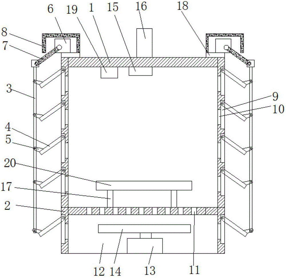
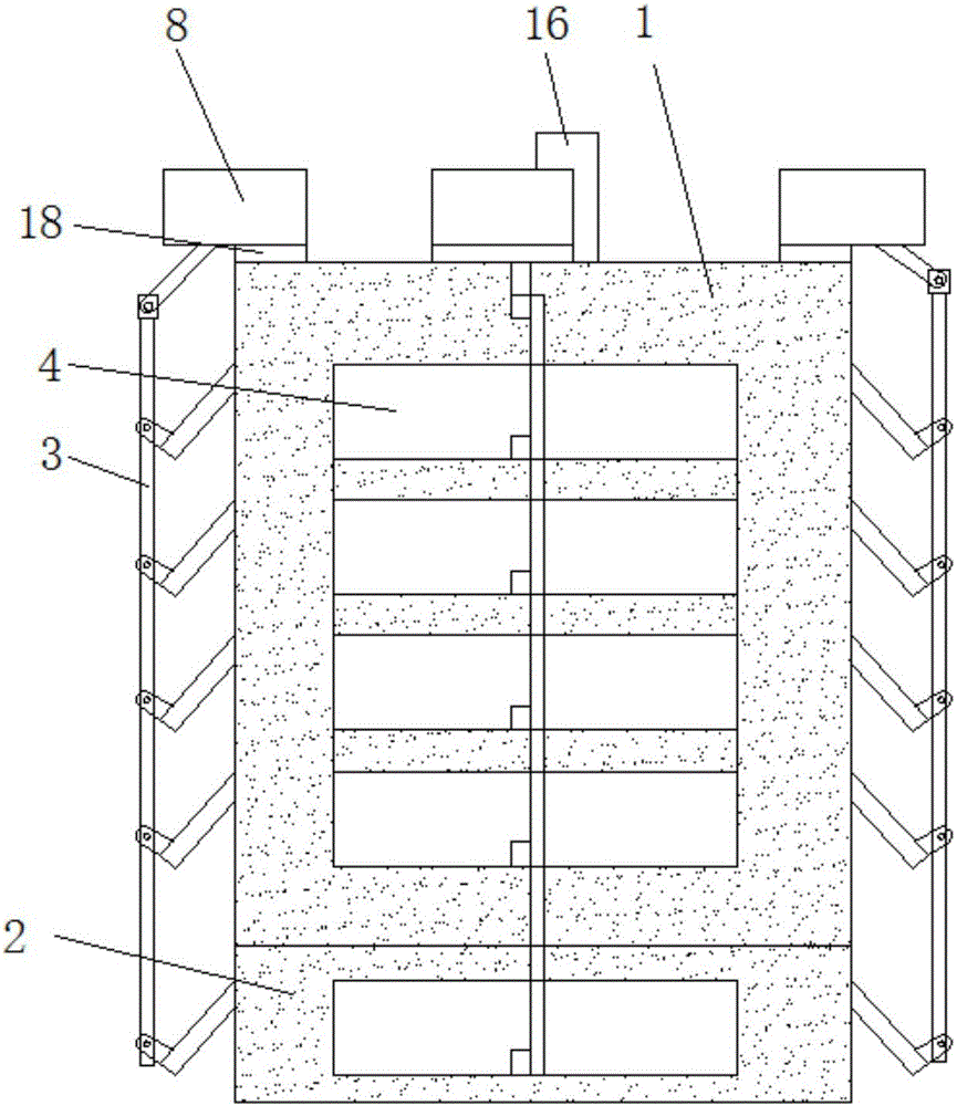
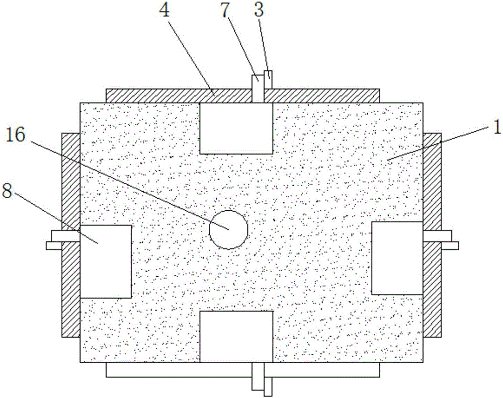
[0015] see Figure 1-3 , the present invention provides a technical solution: a power equipment box with fire-proof and heat-dissipating functions, including a box body 1, a base 2 and a tie rod 3, the box body 1 is installed on the top of the base 2, the box body 1 and the base 2 are provided with outer holes 9 on the sides, the inner sides of the outer holes 9 are provided with inner holes 10 respectively penetrating through the box body 1 and the base 2, an...


PUM


Abstract

The invention discloses a power equipment box with fireproofing and cooling functions. Outer holes are formed in the side surfaces of a box body and a base; inner holes which penetrate through the box body and the base are arranged in the inner sides of the outer holes respectively; a cover plate is in pin connection with the tops of the inner sides of the outer holes; a connection block is arranged at the outer side of the bottom of the cover plate and is hinged with one side of a pull rod; an alarm lamp is arranged at the top of the outer side of the box body; a smoke detector and a controller are arranged at the internal top end of the box body separately; a fan room is arranged in the base; and a first motor, the alarm lamp and a second motor are electrically connected with the controller. The equipment box is capable of controlling the cover plate to close and block the inner holes through the pull rod in a fire, so that air is prevented from entering the box body to achieve the target of controlling the fire; and through coordination of the outer holes and the inner holes, the cover plate can completely block holes of the inner holes when completely covering, so that the sealing effect is better.

Description

technical field [0001] The invention relates to the field of electric power technology, in particular to an electric power equipment box with the function of fire prevention and heat dissipation. Background technique [0002] The outdoor power equipment box is a box used to place various power equipment, which can effectively protect the normal operation of the power equipment installed in the box. The air in the traditional power equipment box does not circulate, and the heat cannot be discharged in time or concentrated and accumulated in one electrical equipment. The cooling efficiency of only opening cooling holes on the power equipment box is low. The power equipment box is usually installed outdoors or under the eaves of a single household. During the peak period of electricity consumption, the electrical load in the power equipment box is relatively high. At this time, the electrical equipment generates a large amount of heat. In addition, most of the electrical equip...

Claims


Application Information

Patent Timeline
Patent Type & Authority Applications(China)
IPC IPC(8): H05K5/02H05K7/20G08B17/10A62C3/16
CPCA62C3/16H05K5/0213H05K7/20145G08B17/10H05K5/03
Inventor 赵全儒何海玲周召敏
Owner 泉州市知产茂业工业设计有限公司
Why Eureka
Try Eureka