Hammering device

A crankshaft and frame technology, applied in the field of beating devices, can solve the problems of low production efficiency, continuous production and processing, and high processing costs, and achieve the effects of improving production efficiency, continuous processing and production, and reducing processing costs

Inactive Publication Date: 2017-05-31
刘正龙
View PDF10 Cites 15 Cited by
  • Summary
  • Abstract
  • Description
  • Claims
  • Application Information

AI Technical Summary

Problems solved by technology

[0004] The object of the present invention is to provide a kind of beating device, to relieve the technology in the prior art that due to manual processing and beating of dried beef, continuous production, processing and manufacturing cannot be carried out, and market demand cannot be met, and there are technologies of low production efficiency and high processing cost. question

Method used


Image

  • Hammering device
  • Hammering device
  • Hammering device

Examples


Embodiment 1

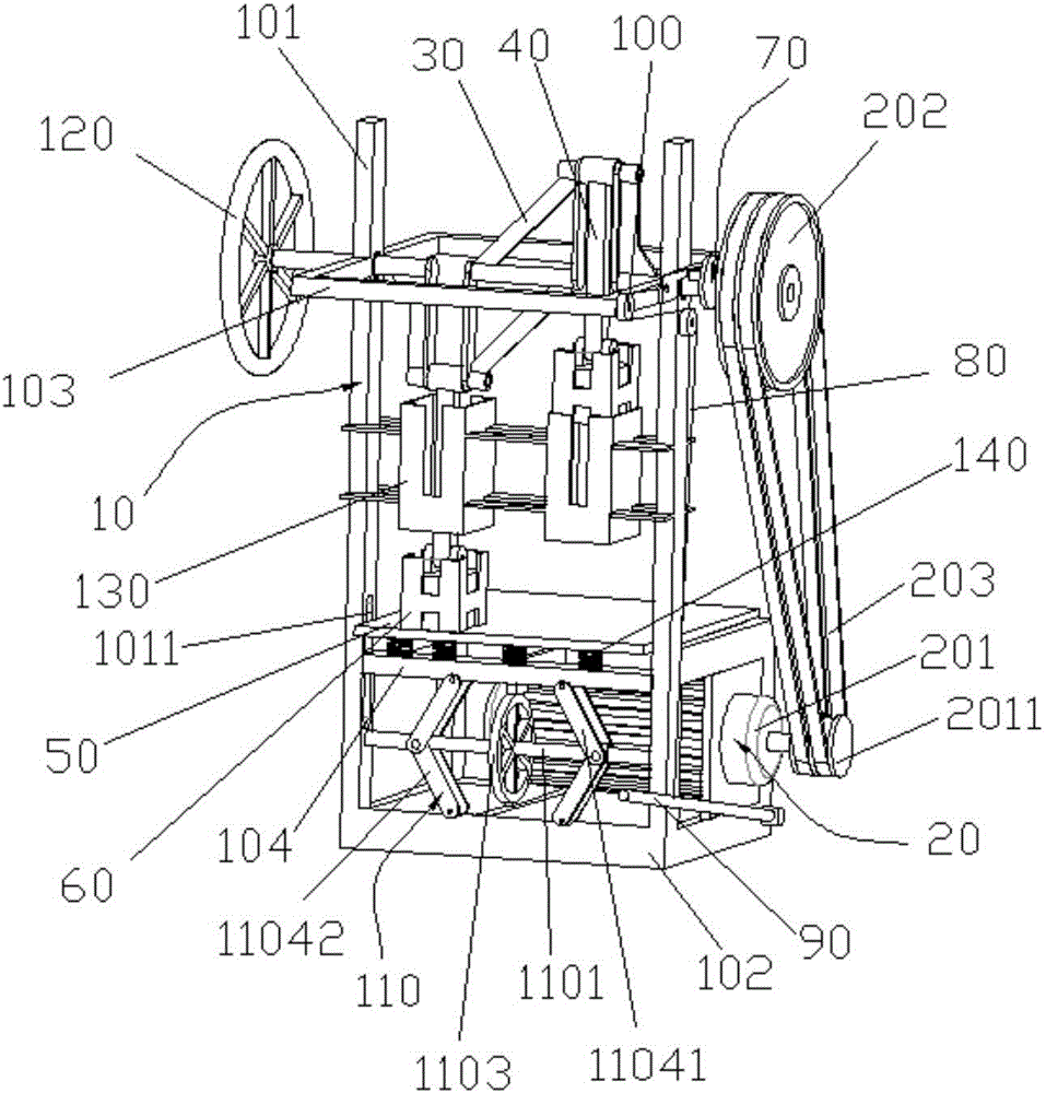
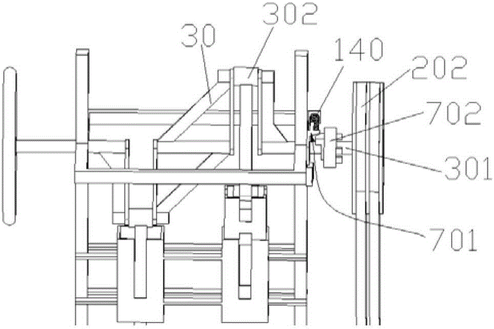
[0046] Such as figure 1 with figure 2 As shown, this embodiment provides a beating device, which includes a frame 10, a power drive unit 20, a crankshaft 30 pivotally connected to the frame 10, and a hammer head connecting rod whose one end is pivotally connected to the connecting rod journal 302 of the crankshaft 30 40 and an object carrier 50 fixed on the frame 10 in a horizontal direction. The other end of the hammerhead link 40 is pivotally connected with a hammer head 60 which is located above the object carrier 50.

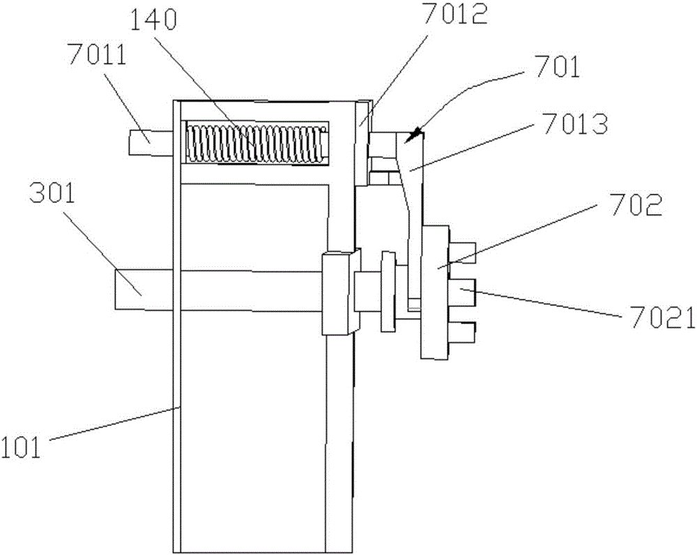
[0047] The power output end of the power drive unit 20 is connected with the main journal 301 of the crankshaft 30, and the main journal 301 of the crankshaft 30 is sleeved with a clutch 70 for controlling the synchronous movement of the crankshaft 30 and the power drive unit 20.

[0048] The beating device includes a frame 10 and a crankshaft 30 pivotally connected to the frame 10. When in use, the staff puts the marinated dried beef on the carrying plate 50. S...

Embodiment 2

[0076] In this embodiment, another beating device is also provided, which includes a frame 10, a conveying unit, a power drive unit 20, a crankshaft 30 pivotally connected to the frame 10, and one end pivotally connected to the connecting rod journal 302 of the crankshaft 30 The hammerhead link 40 and the loading board 50 fixed on the frame 10 in a horizontal direction, the hammerhead 60 is pivotally connected to the other end of the hammerhead link 40, and the hammerhead 60 is located above the loading board 50.

[0077] The power output end of the power drive unit 20 is connected with the main journal 301 of the crankshaft 30, and the main journal 301 of the crankshaft 30 is sleeved with a clutch 70 for controlling the synchronous movement of the crankshaft 30 and the power drive unit 20.

[0078] The conveying unit includes a conveying rack fixed on the frame 10, a transmission wheel pivotally connected to both ends of the conveying rack, a conveyor belt wrapped around the transm...


PUM


Abstract

The invention provides a hammering device and relates to the technical field of food processing. The hammering device comprises a frame, a power driving unit, a crankshaft pivoted on the frame, a hammer head connecting rod pivoted on a journal of a connecting rod of the crankshaft at one end and a carrying plate fixedly arranged on the frame in the horizontal direction. A hammer head is pivoted to the other end of the connecting rod of the hammer head, the hammer head is located above the carrying plate, a power output end of the power driving unit is connected to a main journal of the crankshaft, and a clutch for controlling synchronous movements of the crankshaft and the power driving unit sleeves the main journal of the crankshaft. The hammering device provided by the invention alleviates the technical problem that the production efficiency is low and the processing cost is high in the prior art because cured beef which is manually hammered cannot be continuously processed and manufactured and the market demand cannot be met.

Description

Technical field [0001] The invention relates to the technical field of food processing, in particular to a beating device. Background technique [0002] In order to extend the preservation time of food, people often process food by adding salt and air-drying. Among them, dried beef is a kind of beef preserved food. Because the beef after curing and air drying has better hardness, it cannot be eaten immediately. Therefore, the dried beef is placed on wooden piers or stone platforms in life. People hold the hammer and repeatedly beat the dried beef until it becomes loose and soft before eating. [0003] Although the existing method can beat dried beef to the edible standard, due to manual processing and beating, continuous production and processing cannot be performed, which cannot meet the needs of the market, and there are technical problems of low production efficiency and high processing cost. Summary of the invention [0004] The purpose of the present invention is to provide a...

Claims


Application Information

Patent Timeline
IPC IPC(8): A22C9/00
CPCA22C9/007
Inventor 刘正龙
Owner 刘正龙
Why Eureka
Try Eureka