Mop bucket

A mop bucket and bucket body technology, applied in the field of mop buckets, can solve problems such as inconvenient water changes, and achieve the effect of convenient water changes and simple structure

Inactive Publication Date: 2017-05-31
YUYAO JIJIA ELECTRICAL APPLIANCES
View PDF0 Cites 5 Cited by
  • Summary
  • Abstract
  • Description
  • Claims
  • Application Information

AI Technical Summary

Problems solved by technology

[0004] The problem to be solved by the present invention is to provide a m

Method used


Image

  • Mop bucket

Examples


Embodiment Construction

[0012] The specific implementation manners of the present invention will be further described in detail below in conjunction with the accompanying drawings and embodiments. The following examples are used to illustrate the present invention, but are not intended to limit the scope of the present invention.

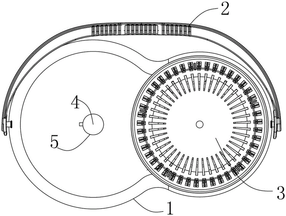
[0013] Such as figure 1 As shown, a mop bucket of the present invention includes a bucket body 1, a handle 2 and a dehydration basket 3, the handle 2 is clamped and arranged on the upper end of the bucket body 1, and the dehydration basket 3 is rotatably arranged on the On the inner side of the barrel body 1 , a through hole 4 is arranged at the bottom of the barrel body 1 , and the through hole 4 is sealed by a sealing plug 5 . The barrel body 1 is oval in shape. The lower end of the dehydration basket 3 is connected with a rotating shaft and a bearing.

[0014] The mop bucket of the present invention has a simple structure, and the through hole is convenient for chang...


PUM


Abstract

The invention provides a mop bucket. The mop bucket comprises a bucket body, a handle and a dehydration basket. The handle is arranged at the upper end of the bucket body. The dehydration basket is rotatably arranged on one side of the bucket body. The bottom of the bucket body is provided with a through hole. The through hole is sealed by a sealing plug. The mop bucket is simple in the structure and water exchange is convenient through the through hole.

Description

technical field [0001] The invention relates to a mop bucket. Background technique [0002] The first thing that distinguishes the rotating mop bucket from the traditional mop bucket is that it can rotate. Through the principle of centrifugal force generated by rotation, a little manpower is used to make the mop have the same effect as drying in a washing machine. It is inconvenient to change the water in the existing mop bucket. Contents of the invention [0003] (1) Technical problems to be solved [0004] The problem to be solved by the present invention is to provide a mop bucket to overcome the inconvenience of changing water in the prior art. [0005] (2) Technical solution [0006] In order to solve the above technical problems, the present invention provides a mop bucket, which includes a bucket body, a handle and a dehydration basket, the handle is clamped and arranged on the upper end of the bucket body, and the dehydration basket is rotatably arranged on the...

Claims


Application Information

Patent Timeline
IPC IPC(8): A47L13/58
CPCA47L13/58
Inventor 应吉安
Owner YUYAO JIJIA ELECTRICAL APPLIANCES
Why Eureka
Try Eureka