Double flanges H-shaped stainless steel valve body multi-way precision forming device

A precision forming, stainless steel technology, applied in valve devices, forging/pressing/hammer devices, manufacturing tools, etc., can solve the problems of complex production process, low production efficiency, inclusions, etc., to achieve simple installation and replacement, strong device compatibility, The effect of low processing cost

Active Publication Date: 2017-05-31
ZHENGZHOU RES INST OF MECHANICAL ENG CO LTD
View PDF7 Cites 24 Cited by
  • Summary
  • Abstract
  • Description
  • Claims
  • Application Information

AI Technical Summary

Problems solved by technology

[0003] At present, this type of stainless steel valve body in foreign countries is mostly formed by casting method. The blank produced by casting method is prone to casting defects such as looseness, shrinkage cavity and inclusion, which makes the mechanical properties of its products much lower than that of forgings.
In addition to the casting method, some domestic manufacturers use the cold drawing process to produce valve body blanks. The valve body blanks produced by this process have a high surface finish and do not require secondary processing. However, the production process is complicated, and it takes 8 - 9 passes of cold drawing, each process must carry out phosphorus saponification treatment, solid solution treatment and replacement of molds, which leads to low production efficiency and high cost
In addition, pickling treatment is required for each rough blank, which will inevitably cause greater environmental pollution

Method used


Image

  • Double flanges H-shaped stainless steel valve body multi-way precision forming device
  • Double flanges H-shaped stainless steel valve body multi-way precision forming device
  • Double flanges H-shaped stainless steel valve body multi-way precision forming device

Examples


Embodiment Construction

[0018] The present invention will be further described below in conjunction with embodiment (accompanying drawing):

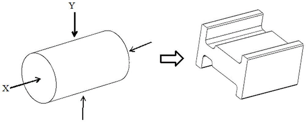
[0019] Such as figure 1 As shown, in this embodiment, the forging is formed by extruding the billet from the horizontal X direction and the vertical Y direction, and the device should be installed on a four-direction forming press.

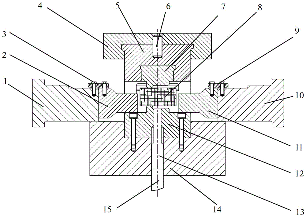
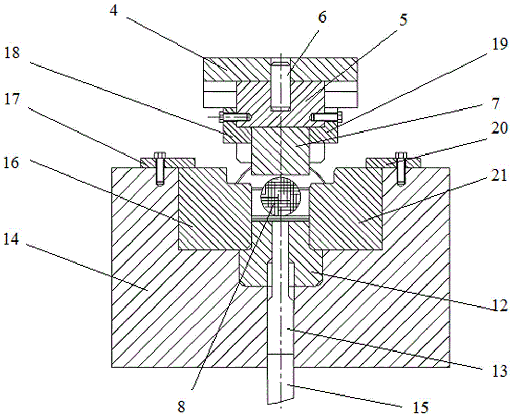
[0020] Such as figure 2 , 3 , shown in 4, double-flange I-shaped stainless steel valve body multidirectional precision forming device of the present invention comprises left extrusion die assembly, right extrusion die assembly, upper extrusion die assembly, four parts of following extrusion die assembly; The compression die assembly includes a left punch connecting rod 1 and a left punch 2; the right extrusion die assembly includes a right punch connecting rod 10 and a right punch 11; the upper extrusion die assembly includes an upper Backing plate 4, punch cushion block 5, upper punch 7; the lower extrusion die assembly includ...


PUM


Abstract

The invention discloses a double flanges H-shaped stainless valve body multi-way precision forming device. The device comprises four parts: a left extruding mold assembly, a right extruding mold assembly, an upper extruding mold assembly and a lower extruding mold assembly. The left extruding mold assembly comprises a left punch connecting rod and a left punch. The right extruding mold assembly comprises a right punch connecting rod and a right punch. The upper extruding mold assembly comprises an upper padding plate, a ram block and an upper punch. The upper padding plate, a ram block and an upper punch are in connection in turn from up to down. The lower extruding mold assembly comprises an die holder and a mold unloading which are in connection successively from down to up and further comprises an ejector beam connecting rod and an ejector beam which successively run through central through holes of the die holder and the mold unloading from bottom up. The double flanges H-shaped stainless valve body multi-way precision forming device is capable of forming forges needed by a single pass, has the advantages of having good forming effect and high efficiency, being easy to install each assembly of the forming device, having low cost of mold materials and low finished cost, having high compatibility of device and forming other complex forges through changing shapes of the mold.

Description

technical field [0001] The invention belongs to a thermal precision forming device in the machinery manufacturing industry, in particular to a multi-directional precision forming device for a double-flange I-shaped stainless steel valve body. Background technique [0002] The double-flange I-shaped stainless steel valve body is widely used in oil and natural gas exploration, refining and pipeline transportation systems. Because it works in harsh environments for a long time, such as high temperature, high pressure, corrosive media, etc., this poses a challenge to the performance of the valve body. Higher requirements to ensure the reliability and safety of the valve during use. [0003] At present, this type of stainless steel valve body in foreign countries is mostly formed by casting method. The blank produced by casting method is prone to casting defects such as looseness, shrinkage cavity and inclusion, which makes the mechanical properties of its products far lower than...

Claims


Application Information

Patent Timeline
Patent Type & Authority Applications(China)
IPC IPC(8): B21K1/24B21J13/02
CPCB21J13/02B21K1/24
Inventor 刘华刘光辉刘百宣孙红星王涛刘丹汪金保
Owner ZHENGZHOU RES INST OF MECHANICAL ENG CO LTD
Why Eureka
Try Eureka