Eureka AIR delivers breakthrough ideas for toughest innovation challenges, trusted by R&D personnel around the world.

Machine tool main shaft module

A machine tool spindle and spindle technology, applied in the field of machine tools, can solve problems such as spindle distortion and deformation, and achieve the effects of reducing distortion and deformation force, high precision and good rigidity

Inactive Publication Date: 2017-05-31
常州铸鼎机械有限公司
View PDF8 Cites 0 Cited by
  • Summary
  • Abstract
  • Description
  • Claims
  • Application Information

AI Technical Summary

Problems solved by technology

[0003] The technical problem to be solved by the present invention is: in order to solve the problem in the prior art that the two ends of the main shaft of the main shaft module are respectively connected to the power input and the power chuck, which causes the main shaft to be easily twisted and deformed, a machine tool main shaft module is now provided, which is applicable For CNC vertical lathes, CNC lathes, drilling machines, milling machines, etc.

Method used


Image

  • Machine tool main shaft module
  • Machine tool main shaft module

Examples


Embodiment 1

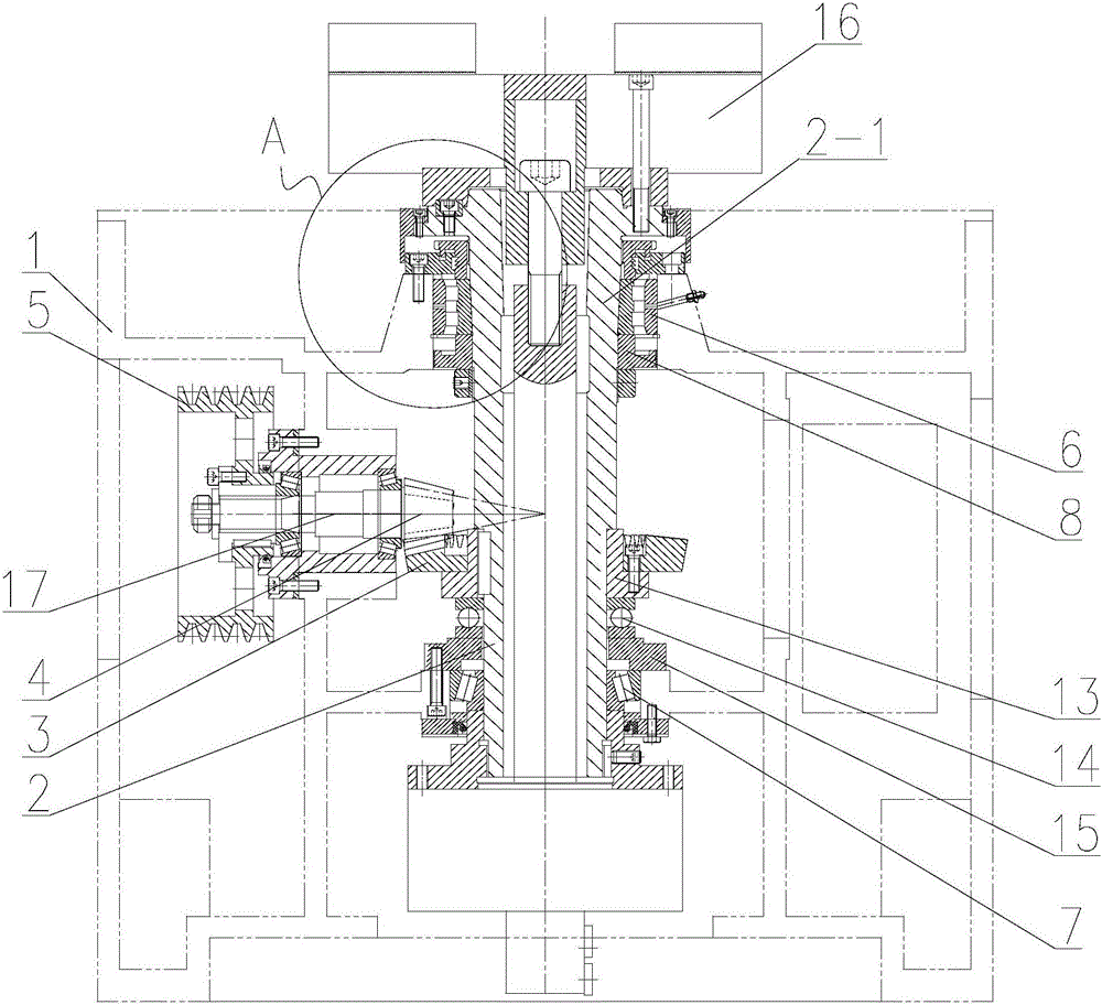
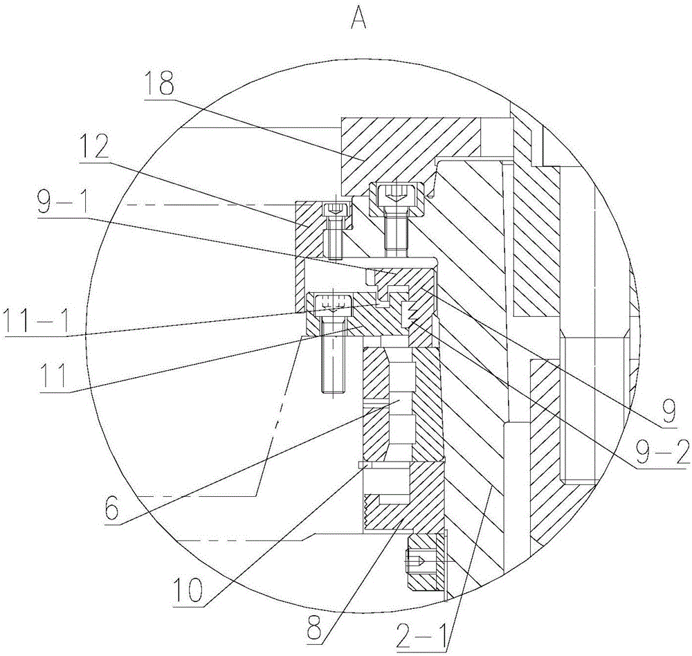
[0021] Such as figure 1 with 2 As shown, a spindle module of a machine tool includes a casing 1 and a spindle 2 rotatably installed in the casing 1. The front end of the spindle 2 is fixed with a connection plate 18 and a chuck 16. The front end and the rear end of the spindle 2 are connected to the casing 1. Bearings are arranged between them, the middle part of the main shaft 2 is fixed with a driven wheel 3, and the transmission shaft 17 is arranged on the side of the main shaft 2 on the box body 1. One end of the transmission shaft 17 is fixed with a pulley 5, and the other end is fixed with a driving wheel. Wheel 4, the driving wheel 4 is connected to the driven wheel 3, the external main motor is connected to the pulley 5 of the transmission shaft 17 through the transmission belt, and the transmission shaft 17 drives the main shaft 2 to rotate through the transmission connection between the driving wheel 4 and the driven wheel 3 and provides certain Reduction ratio.

...


PUM


Abstract

The invention relates to the technical field of machine tools, in particular to a machine tool main shaft module. The machine tool main shaft module comprises a box body, and a main shaft rotationally mounted in the box body; bearings are respectively arranged between the front end and the back end of the main shaft and the box body; a driven wheel is fixed at the middle part of the main shaft; the box body is rotationally provided with a transmission shaft on the side of the main shaft; one end of the transmission shaft is fixed with a belt wheel, and the other end is fixed with a driving wheel; and the driving wheel and the driven wheel are in transmission connection. The machine tool main shaft module breaks through limitations of a traditional lathe main shaft structure, integrates parts on the main shaft as a whole module, facilitates large-scale manufacturing, has such advantages as convenience to assemble and maintain, high precision, good rigidity, high bearing capacity, fast response and low noise, inputs external power from the middle part of the main shaft, reduces the twisting deformation force of the main shaft, reduces the rigidity requirement on the main shaft, improves the rotating precision of the main shaft, prolongs the service life of the main shaft, can provide a certain speed reducing ratio to transmission connection between the driven wheel and the driving wheel, and increases the output torque.

Description

technical field [0001] The invention relates to the technical field of machine tools, in particular to a machine tool spindle module. Background technique [0002] The main shaft module structural component is one of the essential key core components of the CNC machine tool, and is the heart of the CNC machine tool. The external main motor transmits the external power to the main shaft of the machine tool through a belt drive to realize the rotary cutting function of the main shaft. The existing main shaft The main shaft of the module is generally connected to the power at one end and the power chuck at the other end. The main shaft is prone to twisting and deformation, resulting in eccentric rotation of the main shaft and affecting the machining accuracy of the parts. The main drive through the rear end of the main shaft is mainly used for high speed. , Machine tools with a small speed range. Due to the radial force (with pulling force) of the power source acting on the re...

Claims


Application Information

Patent Timeline
Patent Type & Authority Applications(China)
IPC IPC(8): B23B19/02
CPCB23Q1/70
Inventor 殷忠和
Owner 常州铸鼎机械有限公司
Why Eureka
Eureka Blog
Learn More