Gear machining and polishing device

A technology for gears and grinding parts, which is applied in the field of gear processing and grinding devices, and can solve the problems of vibration marks and uneven grinding of saw teeth in gears, etc.

Inactive Publication Date: 2017-05-31
CHONGQING RUNYUE MACHINERY CO LTD
View PDF6 Cites 11 Cited by
  • Summary
  • Abstract
  • Description
  • Claims
  • Application Information

AI Technical Summary

Problems solved by technology

[0004] The present invention provides a gear processing and grinding device in order to solve the uneven grinding force of the saw teeth on the gear, which may easily cause vibration marks on the ground gear.

Method used


Image

  • Gear machining and polishing device
  • Gear machining and polishing device
  • Gear machining and polishing device

Examples


Embodiment Construction

[0016] The present invention will be described in further detail below by means of specific embodiments:

[0017] The reference signs in the accompanying drawings of the specification include:

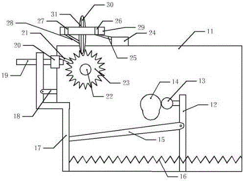
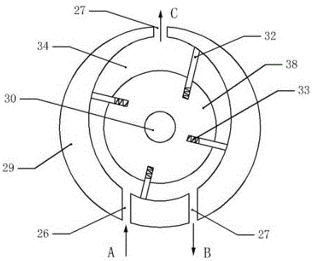
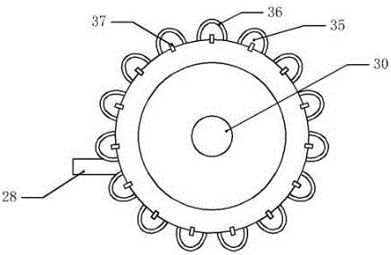
[0018] Frame 11, vertical support plate 12, runner 13, cam 14, connecting rod 15, compression spring 16, support frame 17, elastic rod 18, screw mandrel 19, sliding sleeve 20, push plate 21, transverse shaft 22, gear 23. Blower 24, air inlet pipe 25, air inlet 26, air outlet 27, air outlet pipe 28, blade type air motor 29, rotating shaft 30, grinding part 31, blade 32, spring 33, air chamber 34, air bag 35, fine Sandpaper 36, one-way air vent 37, rotating disk 38.

[0019] Such as figure 1 The shown gear processing and grinding device includes a frame 11 and a support frame 17, a horizontal shaft 22 is fixedly installed on the upper left side of the frame 11, a gear 23 to be processed is installed on the horizontal shaft 22, the support frame 17 is placed in front of the gear 23, and...


PUM


Abstract

The invention relates to a gear treatment device and in particular relates to a gear machining and polishing device. A transverse shaft is fixedly mounted on a rack; a gear is mounted on the transverse shaft; a screw rod with a sliding sleeve is arranged on a supporting frame; the end part of a push plate on the sliding sleeve abuts against the gear; the right end of a connecting rod on the supporting frame is hinged to a vertical supporting plate; a cam is arranged on the vertical supporting plate; the upper end and lower end of a polishing part are connected with a rotary shaft; an air chamber is formed between an inner wall of a blade type pneumatic motor which is rotatably mounted on the rotary shaft, and an outer wall of a rotary table; an air inlet and an air outlet, which are communicated with the air chamber, are formed in a side wall of the pneumatic motor; the air inlet is connected with an air blower and a plurality of grooves are formed in the rotary table; the rotary table is fixedly connected onto the rotary shaft; one end of a blade on the inner wall of the blade type pneumatic motor abuts against the inner wall of the blade type pneumatic motor and the other end of the blade is fixedly connected with a spring; one end, connected with the spring, of the blade is clamped into the groove; the problems that the polishing strength on saw teeth of a gear is not uniform and vibration marks easily form on the polished gear are solved.

Description

technical field [0001] The invention relates to a gear processing device, in particular to a gear processing and grinding device. Background technique [0002] A gear is a mechanical element with teeth on the rim that can continuously mesh to transmit motion and power. The application of gears in transmission has appeared very early. It appears that with the development of production, the stability of gear operation has been paid attention to, and the gear needs to be polished after production. Grinding the saw teeth on the gear is difficult to operate. Generally, the grinding wheel is fixed. Manually adjust the height of the saw gear and then adjust the rotation of the saw gear, so as to grind each saw tooth on the saw gear. The adjustment operation is troublesome and the work low efficiency. [0003] The invention patent of authorized notification number CN 103331489 B discloses a grinding device for saw teeth on a saw gear, which includes a frame on which a saw gear is ...

Claims


Application Information

Patent Timeline
Patent Type & Authority Applications(China)
IPC IPC(8): B23F19/00
CPCB23F19/00
Inventor 曾义杰
Owner CHONGQING RUNYUE MACHINERY CO LTD
Why Eureka
Try Eureka