Automatic boring tapping all-in-one machine

A technology of tapping and drilling mechanism, which is applied in other manufacturing equipment/tools, manufacturing tools, etc., can solve the problems of complex structure and control system, poor workpiece positioning accuracy, and reduced work efficiency, so as to achieve a high degree of automation and a high degree of workpiece accuracy. Accurate positioning, the effect of improving production efficiency

Active Publication Date: 2017-05-31
HUZHOU JIUTONG LOGISTIC MACHINERY
View PDF11 Cites 13 Cited by
  • Summary
  • Abstract
  • Description
  • Claims
  • Application Information

AI Technical Summary

Problems solved by technology

At present, for mechanical drilling and tapping, it is mainly to manually place the workpiece on the workbench and then perform drilling and tapping by hand. When placing the workpiece, the drilling and tapping device is in close contact with the human hand. It increases the risk of being injured by human hands, and the manual working method not only increases the labor intensity but also greatly reduces the work efficiency
An automatic drilling and tapping device described in the Chinese invention patent with the application number of 201510923339.3, comprising: a frame; set on the frame, one end is used to place a workpiece track for workpieces to be processed; On the shelf, the drilling machine and the tapping machine arranged at the other end of the workpiece track in turn; the reclaiming device that brings the workpiece to be processed to the drilling station and the drilled workpiece to the tapping station, all The material reclaiming device includes: a support, a lifting assembly arranged on the support, a reclaiming assembly provided on the elevating assembly, and a pressing assembly for pressing the workpiece to be processed; used to drive the reclaiming device A driving device that moves between the workpiece track and the drilling station and the tapping station; and a controller that controls the coordinated work between the reclaiming device, the driving device, the drilling machine and the tapping machine, wherein The disadvantages are: 1. It cannot be applied to workpieces of various lengths; 2. The structure and control system are complicated, the positioning accuracy of the workpiece is poor, and it is easy to accumulate errors and cause the errors to gradually increase

Method used


Image

  • Automatic boring tapping all-in-one machine
  • Automatic boring tapping all-in-one machine
  • Automatic boring tapping all-in-one machine

Examples


Embodiment

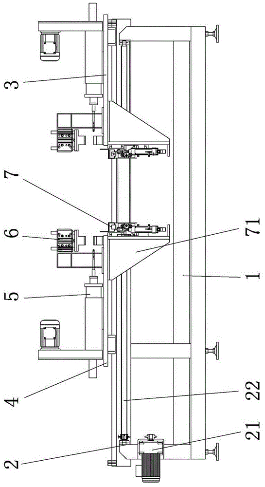
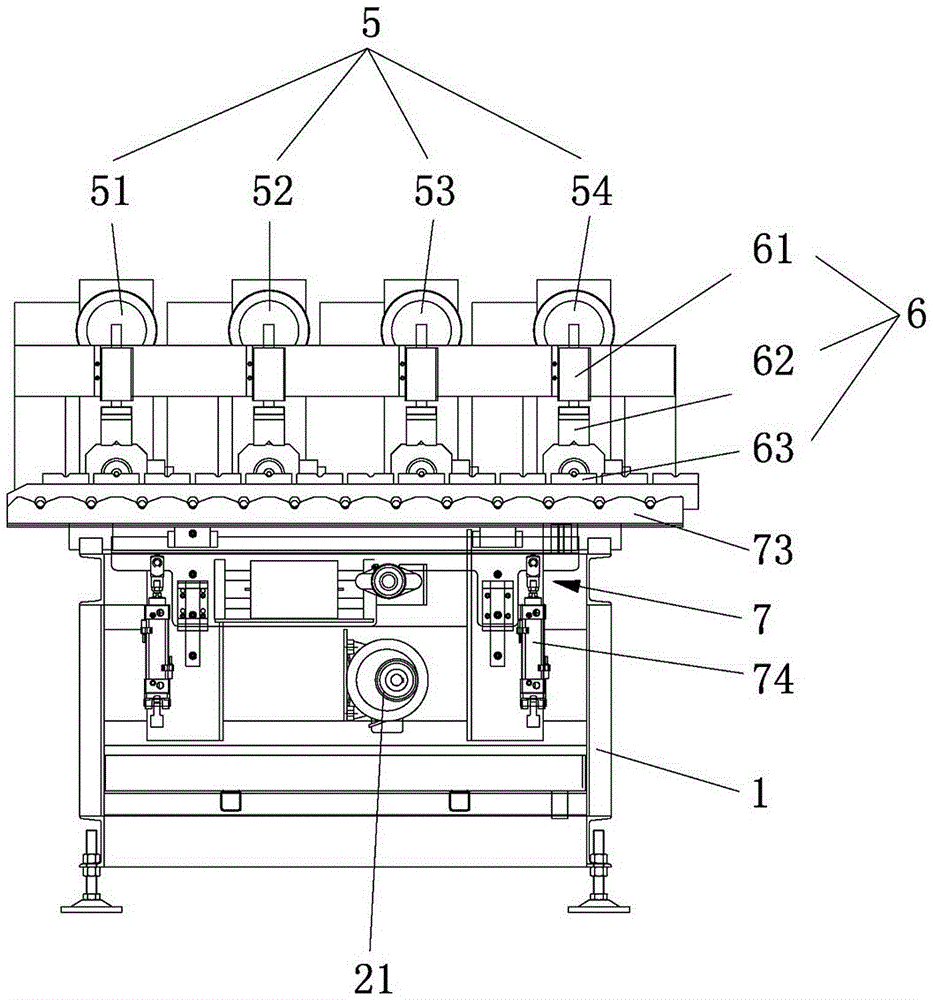
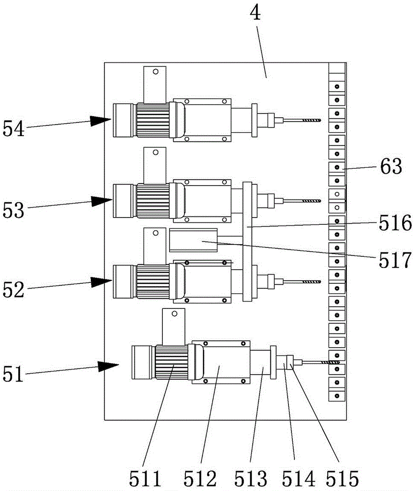
[0023] Example: such as Figure 1 to Figure 5 As shown, an automatic drilling and tapping integrated machine includes a frame 1, and the frame 1 is provided with a fixed workbench 3, a movable workbench 4 and a driving device 2, and the fixed workbench 3 is fixedly installed on the On the frame 1, the movable table 4 is movably installed on the frame 1, and the driving device 2 drives the movable table 4 to move along the frame 1 to adjust the The distance between movable workbench 4 and fixed workbench 3. The driving device 2 includes a motor 21 and a driving screw 22 , the driving screw 22 is rotatably arranged on the frame, and its axial direction is the same as the moving direction of the movable worktable 4 . The bottom of the movable workbench 4 is fixedly connected with a transmission block, and the transmission block is connected with the transmission screw mandrel 22. When the transmission screw mandrel 22 rotates, the transmission block drives the movable workbench ...

Embodiment 2

[0040] Embodiment 2: as Figure 6 As shown, the difference from Embodiment 1 is that translation guide rails 78 are provided with translation stoppers, and the translation stoppers are located on both sides of the translation slider 79, and the translation slider 79 is inside the two translation stoppers. The moving distance is equal to the distance from one station to the next station. The translation limit block includes a fixed limit block 781 and a movable limit block 782. The fixed limit block 781 is fixedly installed on the translation guide rail 78, and the movable limit block 782 is movably installed on the translation guide rail 78, and the movable limit block 782 is fixed on the translation guide rail 78 by a locator, and the distance between the fixed limit block 781 and the movable limit block 782 is adjusted as required. A distance sensor is arranged between the fixed limit block 781 and the movable limit block 782, and an alarm can be issued once the distance cha...

Embodiment 3

[0041] Embodiment 3: The difference from the above embodiments is that the movable workbench 4 and the fixed workbench 3 are also provided with a limit device, and the limit device ensures that the translation distance of the translation frame 73 remains unchanged during the forward and backward translation process. Described spacer device comprises the front spacer bar that is installed on the mounting frame 71, rear spacer bar, upper inductor and lower sensor, and front spacer bar is positioned at the starting position place of translation frame 73, and promptly translation frame 73 is in The positions of the lowest position and the most forward position; the rear limit rod is located at the position where the translation frame 73 moves backwards by one station when it rises from the initial position to the highest position, and the front limit rod and the rear limit rod are all connected with the front drive separately. The limit cylinder for the movement of the limit rod an...


PUM


Abstract

The invention relates to the technical field of automatic machining equipment, in particular to an automatic boring tapping all-in-one machine. The automatic boring tapping all-in-one machine includes a rack, a fixed workbench, a movable workbench, a driving device, and two boring tapping device; one boring tapping device is arranged on the fixe workbench, and the other boring tapping device is arranged on the movable workbench and can move with the movable workbench; fixing devices and circulating feeding devices are arranged between the two boring tapping devices, the circulating feeding devices can transfer a work piece to a boring working station, and can transfer the bored work piece to a tapping working station from the boring working station. The automatic boring tapping all-in-one machine can achieve central hole drilling, boring, tapping and chamfering at the same time, can achieve synchronous machining at two ends, is high in automation level, is simple to operate, can greatly save human resources, can greatly improve the production efficiency, is safe and reliable in feeding, is accurate in work piece positioning, and can avoid inaccurate work piece positioning due to accumulated errors of stepping feeding.

Description

technical field [0001] The invention relates to the technical field of automatic processing equipment, in particular to an automatic drilling and tapping integrated machine. Background technique [0002] With the development of society and economy, industry has increasingly become the backbone of the economy. In the automatic conveying equipment industry, the roller is one of the most important parts. The roller is generally composed of a cylinder body, a bearing end cover and a roller shaft. The installation method of the roller is generally connected to both ends of the roller shaft by bolts. Therefore, during the processing of the roller shaft, both ends of the roller shaft need to be drilled and tapping. At present, for mechanical drilling and tapping, it is mainly to manually place the workpiece on the workbench and then perform drilling and tapping by hand. When placing the workpiece, the drilling and tapping device is in close contact with the human hand. Increased...

Claims


Application Information

Patent Timeline
Patent Type & Authority Applications(China)
IPC IPC(8): B23P23/02
CPCB23P23/02
Inventor 王学勤施长兴
Owner HUZHOU JIUTONG LOGISTIC MACHINERY
Why Eureka
Try Eureka