
An automatic irrational number speed ratio grinding and polishing machine

A technology with irrational numbers and rotational speed ratio, which is applied in the direction of grinding machine tools, grinding racks, grinding/polishing equipment, etc., can solve the problems of corrugation on the polishing surface, the decrease of the surface roughness of the workpiece, and the repetition of the trajectory of the abrasive grains, etc., to improve the surface The effect of improving quality, improving stability, and realizing low-damage processing

Active Publication Date: 2019-11-12
ZHEJIANG UNIV OF TECH
View PDF8 Cites 0 Cited by
  • Summary
  • Abstract
  • Description
  • Claims
  • Application Information

AI Technical Summary

Problems solved by technology

[0004] The purpose of the present invention is to solve the problem that traditional plane grinding and polishing generally adopts rational number rotation speed ratio trajectory for grinding and polishing processing. When the workpiece is processed, the grinding trajectory of the abrasive particles on the workpiece is repeated, which may easily lead to a decrease in the roughness of the surface of the workpiece. Defects such as corrugation and orange peel are formed on the surface, and an automatic irrational number speed ratio grinding and polishing machine is provided. Through irrational number rotation, the problem of repeated abrasive grain trajectory is solved, and uniform grinding without dominant direction is obtained on the surface of the processed workpiece. track

Method used


Image

  • An automatic irrational number speed ratio grinding and polishing machine
  • An automatic irrational number speed ratio grinding and polishing machine
  • An automatic irrational number speed ratio grinding and polishing machine

Examples


Embodiment Construction

[0017] The present invention will be further described below in conjunction with accompanying drawing:

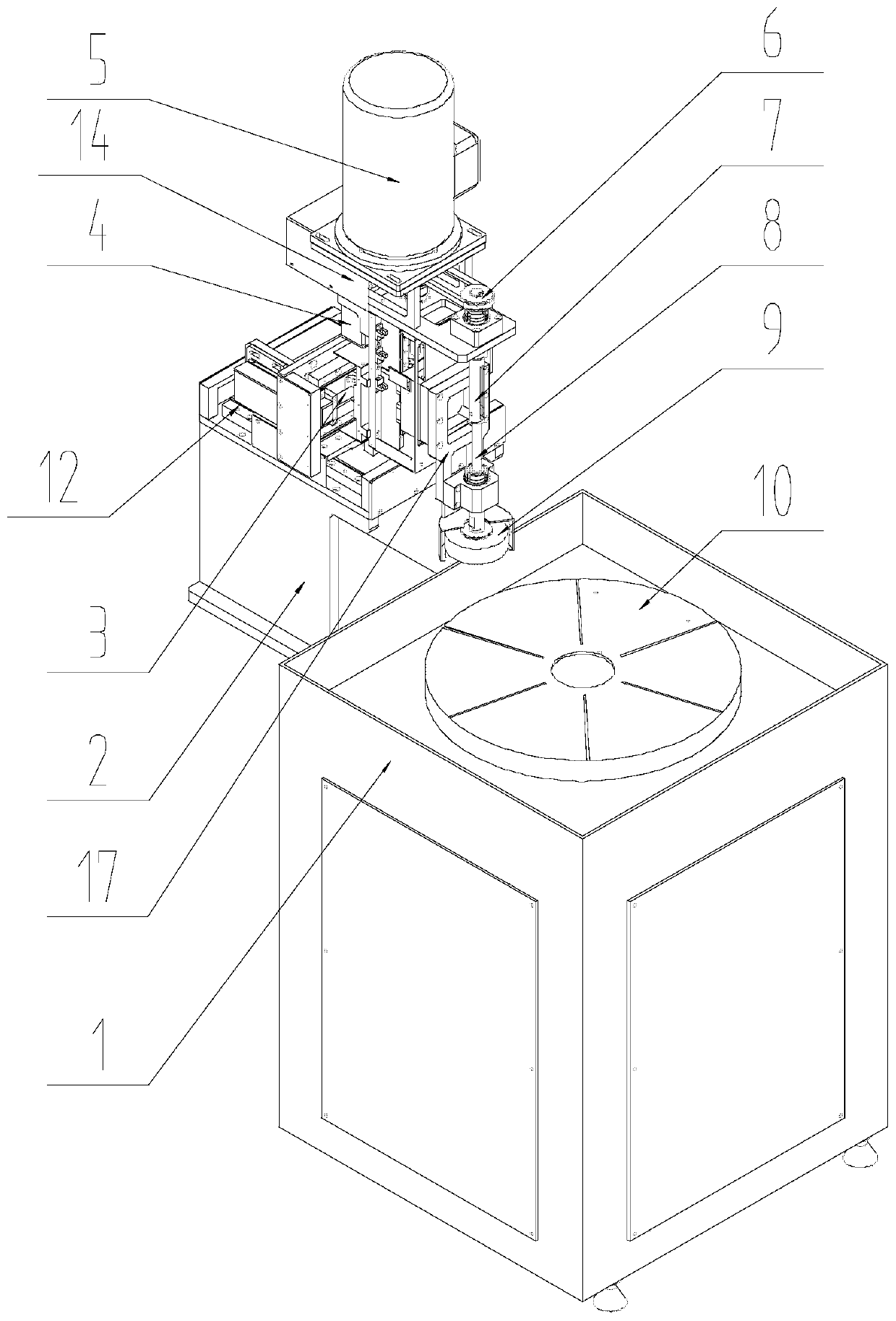
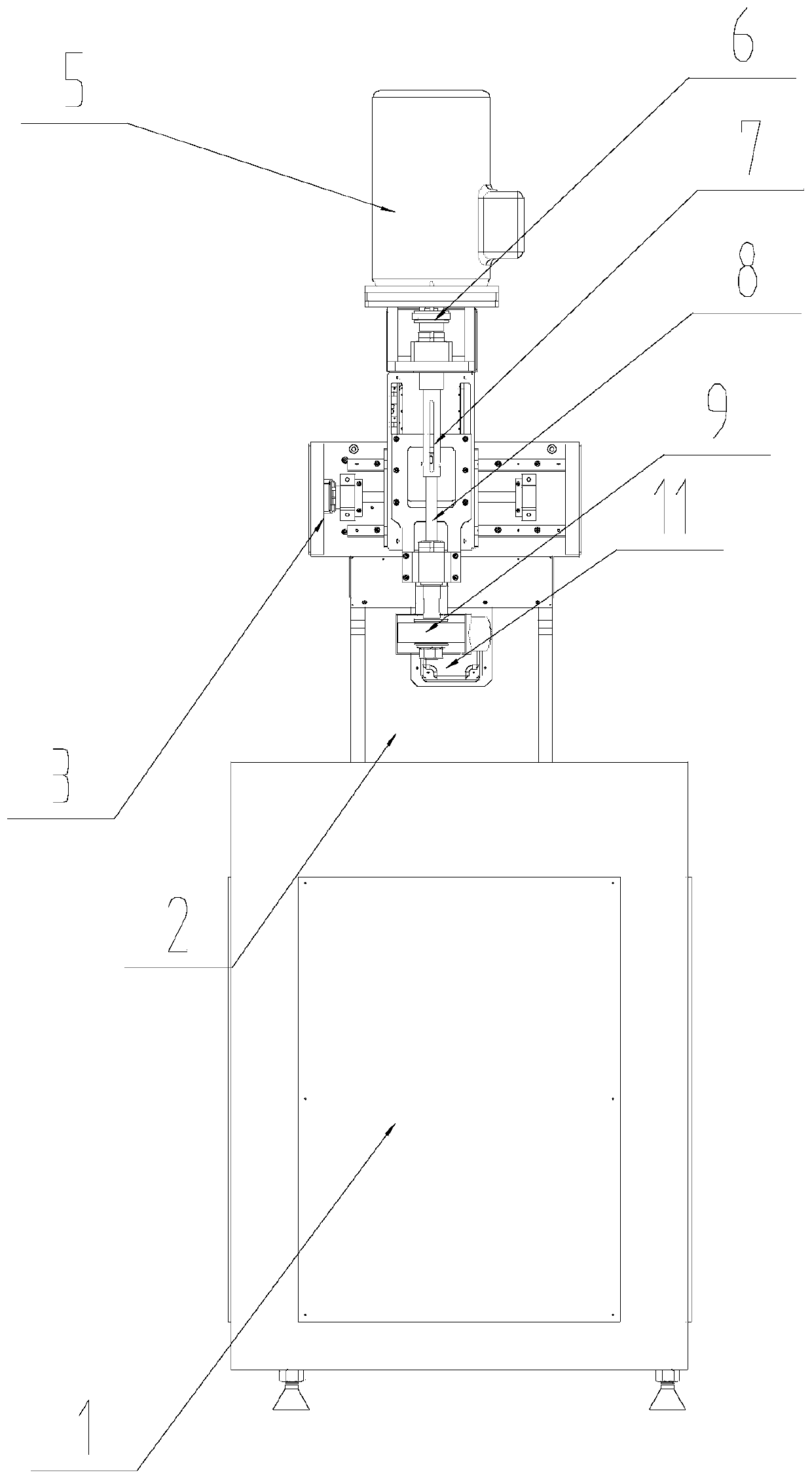
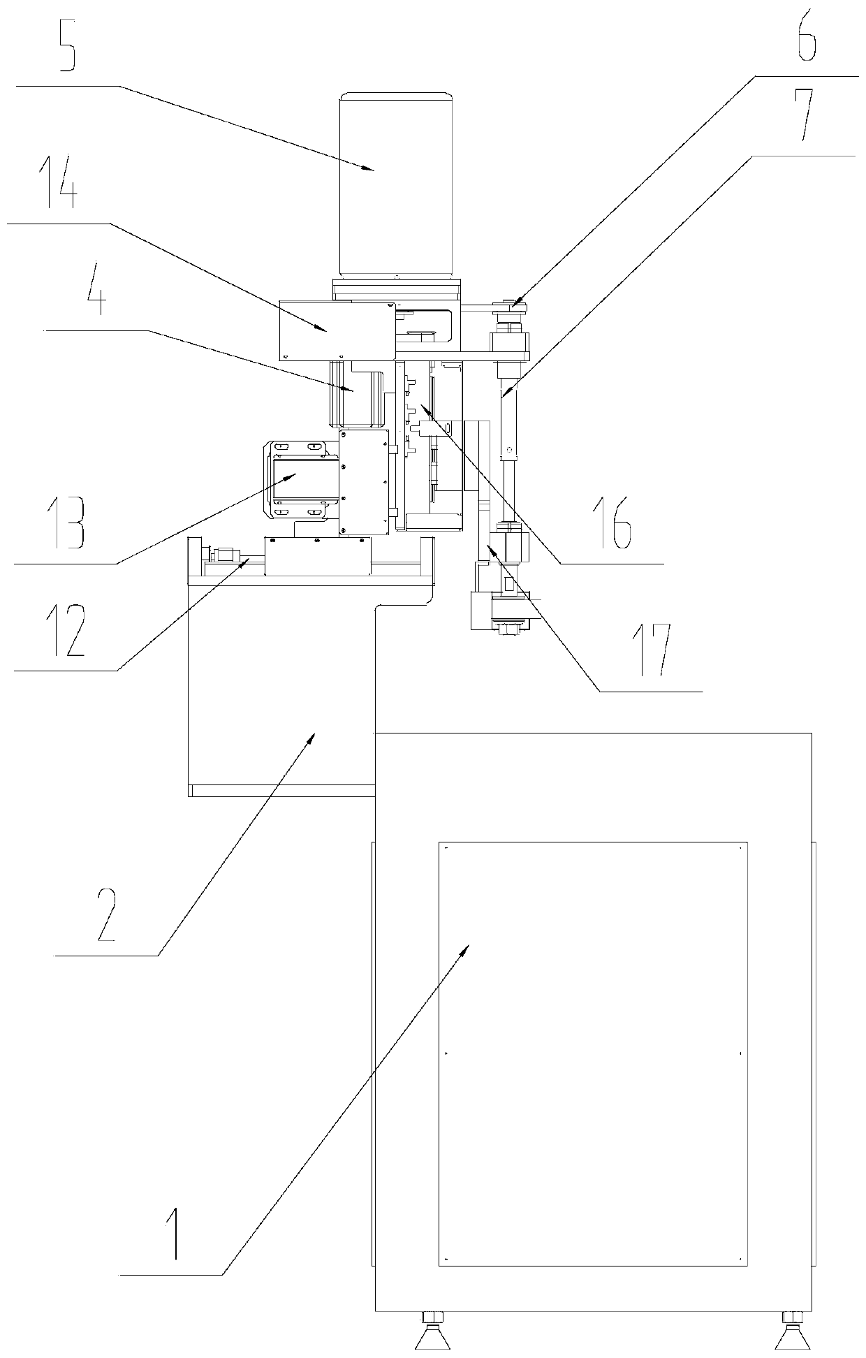
[0018] Such as Figure 1~5 As shown, an automatic irrational number speed ratio grinding and polishing machine includes a grinding machine 1, a first connecting seat 2, an X-axis moving slide 3, a Y-axis moving slide 12, a Z-axis moving slide 16, and an active rotating motor 5 , active synchronous pulley 6, passive synchronous pulley, motor drive shaft 7, driving shaft 8, upper grinding and polishing disc 9, lower grinding and polishing disc 10 and movable plate 17, the first connecting seat 2 is fixed on the grinding and polishing disc by means of screw connection On the side wall of the machine 1, the Y-axis moving slide 12 is installed on the second connecting seat, the X-axis moving slide 3 is installed on the slider of the Y-axis moving slide 12, and the second connecting seat is fixed on the X-axis moving slide On the slide block of table 3, the Z-axis moving slide t...


PUM


Abstract

The invention discloses an automatic irrational number speed ratio grinding and polishing machine. The automatic irrational number speed ratio grinding and polishing machine comprises a traditional grinding machine, a connecting seat, an X-axis movable sliding table, a Y-axis movable sliding table, a Z-axis movable sliding table, a driving rotation motor, a driving synchronous pulley, a driven synchronous pulley, a motor driving shaft, a driving shaft, an upper grinding and polishing disc, a lower grinding and polishing disc and a movable plate. According to the automatic irrational number speed ratio grinding and polishing machine, irrational number rotation is conducted through the driving rotation motor, the driving shaft is controlled to conduct irrational number rotation, the requirement of the upper grinding and polishing disc and the lower grinding and polishing disc for the irrational number speed ratio can be met, thus, the problem that grinding paths of grinding particles on a workpiece are repeated under the condition of the rational number speed ratio is solved, the surface quality of planar grinding machining is improved, and ultra-smooth and low-damage machining of the surface of the workpiece is achieved; and through a strip-shaped hole in the motor driving shaft, the situation that an upper grinding disc spindle and a lower grinding disc spindle are locked when the feeding amount is too large can be effectively prevented, and the safety of grinding and polishing is improved.

Description

technical field [0001] The invention relates to the technical field of ultra-compact grinding and polishing, and more specifically, relates to an automatic grinding and polishing machine with an irrational number speed ratio. Background technique [0002] The current ultra-precision machining technology is based on the premise of not changing the physical properties of the workpiece material to obtain very high shape accuracy, dimensional accuracy, surface roughness, and surface integrity (less surface damage, including residual stress, tissue changes, microcracks, etc.) and other defects) as the goal, it is an important support for cutting-edge technology industries such as aerospace, weapons and national defense, and optoelectronic information. As an important means of ultra-precision machining, grinding and polishing uses fine abrasive grains as the processing medium. Grinding is usually used as a process before polishing. The purpose is to improve the surface accuracy o...

Claims


Application Information

Patent Timeline
Patent Type & Authority Patents(China)
IPC IPC(8): B24B37/08B24B37/34B24B47/12B24B41/02
CPCB24B37/08B24B37/34B24B41/02B24B47/12
Inventor 文东辉陈珍珍章少杰鲁聪达金明生袁巧玲
Owner ZHEJIANG UNIV OF TECH
Learn More