Supercharge Your Innovation With Domain-Expert AI Agents!

Accurate sand conveying device and sand conveying method

A sand feeding and precise technology, which is applied in the direction of abrasive feeding devices, abrasive materials, metal processing equipment, etc., can solve the problem of sand supply continuity, randomness, difficulty in ensuring accurate control and reliability of sand supply, and sieve hole discharge The problem of inconsistency between the level and the degree of clogging can be achieved, and the effect of improving the accuracy and stability of sand supply can be achieved.

Inactive Publication Date: 2017-05-31
NANJING UNIV OF AERONAUTICS & ASTRONAUTICS
View PDF5 Cites 4 Cited by
  • Summary
  • Abstract
  • Description
  • Claims
  • Application Information

AI Technical Summary

Problems solved by technology

This method has some disadvantages: First, the sand particles will easily block the throat position of the electronic valve and flowmeter, thus affecting the continuity of sand supply
The sand particles in nature are almost all coarse sand, which is a kind of solid particles with poor fluidity. There is no equipment such as agitator or vibrator to evacuate the sand plugging phenomenon in the place where the metering flow pipe is gradually narrowed and the valve is narrowed. Sand particles are very prone to clogging, which affects the continuity of sand supply
Second, it is difficult to accurately control the amount of sand supplied by this method
The disadvantage of this method is that it is difficult to accurately control the amount of sand supply, and the reliability of sand supply is not high.
First of all, due to the irregular geometric shape of each sand particle, the discharge degree and clogging degree of each sieve hole will be inconsistent, and under the action of the pressure in the storage tank, all the sieve holes may even be severely blocked; secondly , the amount of sand supplied depends on the vibration parameters of the vibrator, and the situation of screen hole clogging is changing in real time, the vibration parameters will inevitably change in real time, and the time required for this change process and the randomness of the sand under the screen hole will be difficult Ensure precise control and reliability of sand supply

Method used


Image

  • Accurate sand conveying device and sand conveying method
  • Accurate sand conveying device and sand conveying method
  • Accurate sand conveying device and sand conveying method

Examples


Embodiment Construction

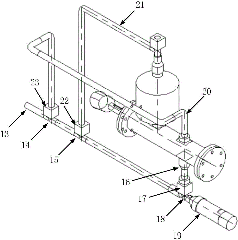
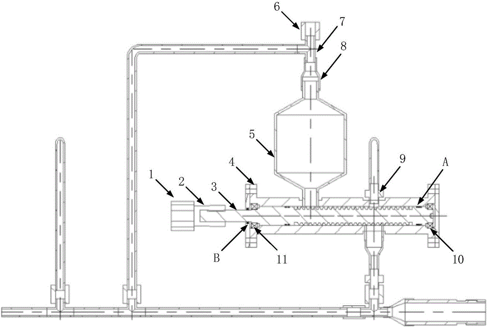
[0023] Attached below figure 1 , attached figure 2 , attached image 3 And attached Figure 4 The specific embodiment of the present invention will be further described.

[0024] The invention is an accurate sand supply device suitable for high pressure environment. The right side of the main airflow input pipe 13 is a three-way pipe 14; the right side of the three-way pipe 14 is a four-way pipe, which is then connected to the three-way pipe 15; the right side of the three-way pipe 15 is a four-way pipe, which is then connected to the three-way pipe 18; the right side of the tee pipe 18 is the main airflow output pipe 19; the airflow flowing through the pipelines 13, 14, 15, 18 and 19 is the main airflow with higher pressure.

[0025] The upper side of the three-way pipe 14 is connected with a solenoid valve 23, and the upper side of the solenoid valve 23 is connected with an auxiliary sand-discharging airflow guide pipe 20;

[0026] The upper side of the three-way pipe ...


PUM


Abstract

An accurate sand conveying device comprises a main airflow inlet pipe, a main airflow outlet pipe, a sand discharging pipe, a screw cylinder, a sand storage container, a pressure balance pipe, and an auxiliary sand-discharging airflow guiding pipe, wherein the pressure balance pipe is used for guiding airflow to flow into the sand storage container, and sand in the sand storage container can enter the screw cylinder smoothly through the pressure balance pipe; a communicating port of the auxiliary sand-discharging airflow guiding pipe and the screw cylinder is located over the sand discharging pipe and used for downwards guiding airflow into the screw cylinder; and a screw extending in the axial direction of the screw cylinder is arranged in the screw cylinder, and the amount of conveyed sand can be adjusted accurately only by changing the rotating speed of the screw.

Description

technical field [0001] The invention relates to the field of fine particle transportation and powder transportation under pressure environment, and also relates to the field of sandblasting test. Background technique [0002] Sand supply devices are often used in industrial production to transport sand for processing; for some sandblasting tests, sand supply devices are also used. In the sandblasting process and sandblasting test, the sand supply device is required to automatically and continuously deliver sand to the sandblasting equipment, making the process and test more efficient. However, no matter in any sand supply application, accurate sand supply is an important prerequisite for the sand supply device. In the supersonic sandblasting test, in order to make the sand particles finally reach the supersonic state, it is necessary to fully mix the sand particles and high-pressure gas (the pressure value is usually set above 3MPa) in an environment with a relatively low a...

Claims


Application Information

Patent Timeline
Patent Type & Authority Applications(China)
IPC IPC(8): B24C7/00
CPCB24C7/0046B24C7/0092
Inventor 颜诚陈伟赵振华
Owner NANJING UNIV OF AERONAUTICS & ASTRONAUTICS
Features
  • R&D
  • Intellectual Property
  • Life Sciences
  • Materials
  • Tech Scout
  • Unparalleled Data Quality
  • Higher Quality Content
  • 60% Fewer Hallucinations
Learn More