
Gear assisted-control clutch device

A technology for auxiliary control and clutch devices, applied to clutches, control devices, mechanically driven clutches, etc., can solve the problems of complex operation, slow speed increase, and inability to complete high-speed gear grabbing, so as to reduce the amount of operation and prevent burnout

Pending Publication Date: 2017-05-31
慕彩霞
View PDF5 Cites 2 Cited by
  • Summary
  • Abstract
  • Description
  • Claims
  • Application Information

AI Technical Summary

Problems solved by technology

[0002] Driving a car with automatic transmission only needs to step on the brake, put it in the driving gear, and then release the brake to complete the start of the car. There is no need to step on the clutch or change gears during driving. However, since the car with automatic transmission is installed with automatic transmission box, so the cost is high, and the torque converter is used to transmit kinetic energy, which has more energy loss, not only slow speed increase, but also high fuel consumption, and it is impossible to switch to low gear when encountering a slippery road or brake failure. Using the engine to brake, there is a certain potential safety hazard
[0003] As we all know, manual transmission cars are cheap, fast, and low fuel consumption. In case of emergency, you can grab a low gear and use the engine to brake. The driver's left foot was sleepy and exhausted
At present, there are many kinds of electronically controlled clutch devices on the market, all of which are controlled by the driving computer to drive the motor to drive the clutch to separate or slowly combine. Although it can avoid stepping on the clutch with the left foot, but because the device needs to be installed with too many sensors, the cost increases. Installation A set costs about 3,000 yuan, and the device cannot accurately judge the driver's intentions, resulting in some cases of coasting in neutral, and in case of emergencies, it is impossible to complete high-speed gear shifting, which poses a safety hazard

Method used


Image

  • Gear assisted-control clutch device

Examples


Embodiment Construction

[0016] The present invention will be described in further detail below in conjunction with the accompanying drawings.

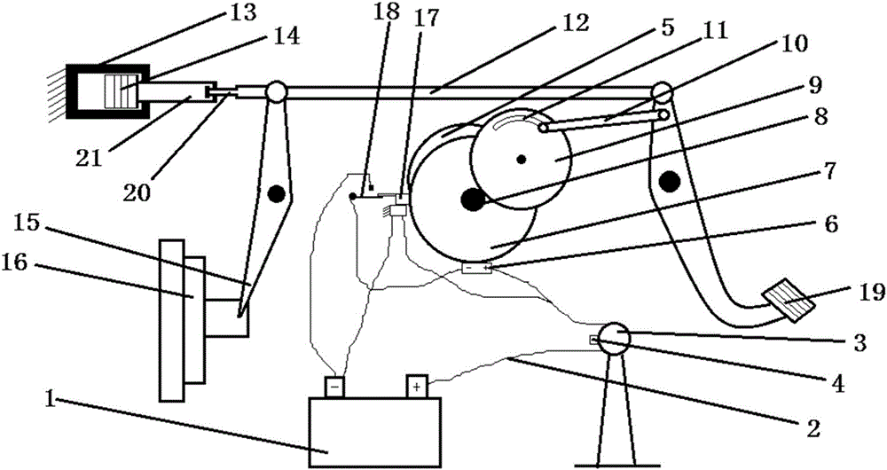
[0017] see figure 1 , the present invention structurally includes a shift fork 15 connected to a clutch 16 to perform shifting, the shift fork 15 is connected to a clutch pedal 19 for driving it to perform a shifting action through a pull rod 12, and one end of the clutch pedal 19 connected to the pull rod 12 is also connected to a An electronically controlled combined gear mechanism capable of driving the pull rod 12 to move. Wherein, the electronically controlled combination gear mechanism includes a thrust rod 10 connected to a clutch pedal 19 at one end, and the other end of the thrust rod 10 is installed in a thrust rod track groove 11 provided on the clutch drive wheel 9, and the thrust rod track groove 11 is for driving with the clutch. Wheel 9) concentric arc grooves. The center of the limiting wheel 7 is provided with a central gear 8, the clutch d...


PUM


Abstract

The invention discloses a gear assisted-control clutch device. The gear assisted-control clutch device comprises a shifting fork which is connected with a clutch to shift gears, wherein the shifting fork is connected with a clutch pedal used for driving the shifting fork to perform actions of shifting the gears through a pull rod, and an electronic control combined gear mechanism which further can drive the pull rod to act is further connected at one end, connected with the pull rod, of the clutch pedal. The electronic control combined gear mechanism comprises a thrust lever of which one end is connected with the clutch pedal, the other end of the thrust lever is mounted in a thrust lever track groove opened in a clutch drive wheel, a center gear is arranged in the center of a limit wheel, the clutch drive wheel is meshed with the center gear, the limit wheel is mounted at the output shaft of a motor. One end, connected with the shifting fork, of the pull rod is connected with a piston rod of a hydraulic buffer through a limit lever. The gear assisted-control clutch device disclosed by the invention has a simple structure and low cost and keeps the advantages of speed increase and low fuel consumption of a manual gear, and further can prevent a left foot from treading the clutch for a long time and can grab the low gear at a high speed in emergency, thereby being safe and reliable.

Description

technical field [0001] The invention belongs to the field of automobile control, and in particular relates to a gear auxiliary control clutch device. Background technique [0002] Driving a car with automatic transmission only needs to step on the brake, put it in the driving gear, and then release the brake to complete the start of the car. There is no need to step on the clutch or change gears during driving. However, since the car with automatic transmission is installed with automatic transmission box, so the cost is high, and the torque converter is used to transmit kinetic energy, which has more energy loss, not only slow speed increase, but also high fuel consumption, and it is impossible to switch to low gear when encountering a slippery road or brake failure. To use engine braking, there is a certain potential safety hazard. [0003] As we all know, manual transmission cars are cheap, fast, and low fuel consumption. In case of emergency, you can grab a low gear and...

Claims


Application Information

Patent Timeline
Patent Type & Authority Applications(China)
IPC IPC(8): B60K23/02F16D48/06F16D48/10
CPCF16D48/064F16D48/068F16D48/10B60K23/02F16D2023/126
Inventor 慕彩霞曹许明
Owner 慕彩霞
Learn More