
Vertical take-off and landing fixed-wing unmanned aerial vehicle

An unmanned aerial vehicle, vertical take-off and landing technology, applied in the field of aircraft, can solve the problems of short flight range and flight time, strict requirements for take-off and landing conditions, slow flight speed of rotorcraft, etc., to achieve high cruising speed, rapid take-off and landing, Low fuel consumption

Inactive Publication Date: 2017-05-31
CHANGCHUN INST OF OPTICS FINE MECHANICS & PHYSICS CHINESE ACAD OF SCI
View PDF4 Cites 29 Cited by
  • Summary
  • Abstract
  • Description
  • Claims
  • Application Information

AI Technical Summary

Problems solved by technology

[0003] The purpose of the present invention is to propose a vertical take-off and landing fixed-wing unmanned aerial vehicle, which solves the problems of strict take-off and landing conditions for fixed-wing aircraft and slow flight speed, short flight range and flight time of rotorcraft in the prior art

Method used


Image

  • Vertical take-off and landing fixed-wing unmanned aerial vehicle
  • Vertical take-off and landing fixed-wing unmanned aerial vehicle
  • Vertical take-off and landing fixed-wing unmanned aerial vehicle

Examples


Embodiment Construction

[0025] Embodiments of the present invention will be further described below in conjunction with the accompanying drawings.

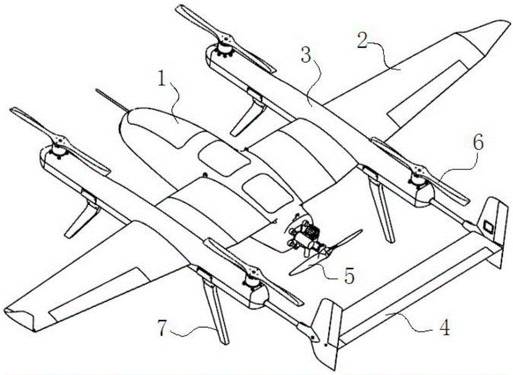
[0026] See attached figure 1 - attached Image 6 , a kind of vertical take-off and landing fixed-wing unmanned aerial vehicle of the present invention comprises:

[0027] A fixed-wing structural system, the fixed-wing structural system includes a fuselage 1, a wing 2 and an empennage 4 that are connected together in a centralized connection manner, and two symmetrically arranged wings 2 are respectively equipped with a rotor support structure 3. The empennage 4 includes two vertical tails and a horizontal tail, the two vertical tails are respectively connected to one end of the horizontal tail, and the two vertical tails are respectively fixed by a connecting rod and the wing 2 threaded connection;

[0028] A fixed-wing power system, the fixed-wing power system includes a single-cylinder two-stroke engine fixed at the end of the fuselage 1 and a propel...


PUM


Abstract

The invention provides a vertical take-off and landing fixed-wing unmanned aerial vehicle, which belongs to the technical field of aircrafts. The purpose is to solving problems that the take-off and landing condition of a fixed-wing aircraft is harsh, the loitering speed of a rotor craft is low and the endurance of the rotor craft is short in the prior art are solved. The vertical take-off and landing fixed-wing unmanned aerial vehicle comprises a fixed-wing structure system, a fixed-wing power system, a rotor structure and power system, a rotor structure supporting piece as well as a flight control system and an avionic system, wherein the fixed-wing power system comprises a single cylinder two-stroke engine and a propeller A, which are fixed at the tail end of an aerial vehicle body; a power output end of the engine is connected with the propeller A; the rotor structure and power system is arranged on the fixed-wing structure system; the rotor structure and power system comprises a motor, an electronic speed controller and propellers B; the motor is electrically connected with the electronic speed controller; an output end of the motor is connected with the propellers B; four propellers B are respectively arranged on the upper end surfaces of two supporting rods of the fixed-wing structure system; the propeller A is perpendicular to the propellers B; the rotor structure supporting piece is fixed at the upper end of a wing of the fixed-wing structure system and used for mounting a rotor power system; and the flight control system and the avionic system are used for controlling the flight path and posture of the unmanned aerial vehicle.

Description

technical field [0001] The invention belongs to the technical field of aircraft, and in particular relates to a vertical take-off and landing fixed-wing unmanned aircraft. Background technique [0002] Traditional unmanned aerial vehicles can be divided into two types: fixed-wing aircraft and rotary-wing aircraft. Fixed-wing aircraft fly fast, and have a long range and flight time. According to the size of the model, it can take off by hand throwing, catapulting or sliding, and land by opening the parachute, hitting the net or sliding, but the general take-off and landing conditions demanding. The flying speed of the rotorcraft is slow, but because of its regular fuselage structure and simple flight principle, it can use the rotor to take off and land vertically, and hover in the air with a stable attitude. Both fixed-wing aircraft and rotary-wing aircraft have their own shortcomings and cannot fully meet the needs. Contents of the invention [0003] The purpose of the ...

Claims


Application Information

Patent Timeline
IPC IPC(8): B64C1/00B64C3/14B64C3/20B64C27/26B64C29/00
CPCB64C1/00B64C3/14B64C3/20B64C27/26B64C29/0025B64U10/25B64U50/19B64U2201/20B64U10/10
Inventor 高九州李艳辉董文辉张恩阳王元超
Owner CHANGCHUN INST OF OPTICS FINE MECHANICS & PHYSICS CHINESE ACAD OF SCI
Learn More