Drive mechanism for trailing edge flaps of variable-speed rigid rotor

A drive mechanism and variable speed technology, applied in the field of intelligent drive mechanism, can solve the problems that it is difficult to meet the vibration reduction requirements of variable speed helicopter rotors, and achieve the effects of light weight, high reliability, and increased bending deformation

Pending Publication Date: 2017-05-31
NANJING UNIV OF AERONAUTICS & ASTRONAUTICS
View PDF6 Cites 3 Cited by
  • Summary
  • Abstract
  • Description
  • Claims
  • Application Information

AI Technical Summary

Problems solved by technology

The operating speed of the variable speed helicopter rotor will vary in a large range with different working conditions, and the frequency of the rotor vibration load

Method used


Image

  • Drive mechanism for trailing edge flaps of variable-speed rigid rotor
  • Drive mechanism for trailing edge flaps of variable-speed rigid rotor
  • Drive mechanism for trailing edge flaps of variable-speed rigid rotor

Examples


Embodiment Construction

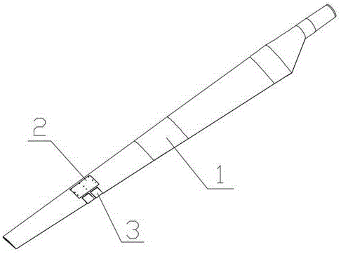
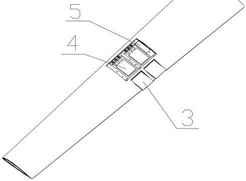
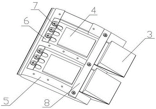
[0027] Such as Figure 1-7 As shown, the drive mechanism disclosed in the present invention is installed inside the rotor blade 1 to provide fixed support for the skin cover of the drive mechanism; its structure mainly includes a fixed frame 5, a driver, a trailing edge winglet 3 and a The briquetting block 6, wedge block 8 and steel rod 15;

[0028] Wherein, the upper and lower surfaces of the fixed frame 5 are fitted with the skin of the rotor blade 1, and the front end of the fixed frame is a leading edge fixed girder parallel to the span direction of the rotor blade, and the two ends and the middle of the leading edge fixed girder can be fixed as required. Arrange the reinforced rib parallel to the chord direction of the rotor blade, the middle and lower part of the trailing edge of the reinforced rib runs through a trailing edge beam parallel to the fixed beam at the leading edge, and the fixed beam at the leading edge, the reinforced rib and the beam at the trailing edge...


PUM


Abstract

The invention discloses a drive mechanism for trailing edge flaps of a variable-speed rigid rotor comprising a fixing frame, a driver, trailing edge flaps and pressing blocks, a wedge block and a steel bar matched with the fixing frame, wherein the driver comprises driver base steel sheets and piezoelectric fiber sheets affixed to the driver base steel sheets; the rear ends of the driver base steel sheets are connected to the trailing edge flaps and the front ends of the driver base steel sheets are fixed to the body of the fixing frame by virtue of the pressing blocks; the upper surface of the portion, between each piezoelectric fiber sheet and each trailing edge flap, of each driver base steel sheet is in contact with the wedge block on the body of the fixing frame, and the lower surface of the portion, between each piezoelectric fiber sheet and each trailing edge flap, of each driver base steel sheet is in contact with the steel bar on the body of the fixing frame; and the steel bar and the wedge block clamp the drive base steel sheets to form revolute prismatic joints. The drive mechanism for the trailing edge flaps of the variable-speed rigid rotor is used for driving the deflection motion of the trailing edge flaps, and the additional aerodynamic load caused by the deflection motion of the trailing edge flaps is used to counteract a part of the vibration load of the variable-speed rigid rotor to achieve the purpose of vibration reduction.

Description

technical field [0001] The invention belongs to an intelligent driving mechanism in the field of helicopters, and in particular relates to an active deformation trailing edgelet light-weight driving mechanism suitable for variable-speed rigid rotors. Background technique [0002] Helicopters have been widely used in military and civilian fields because of their high-efficiency hovering, low-speed forward flight and other performances that fixed-wing aircraft do not have. However, compared with fixed-wing aircraft, conventional configuration helicopters have obvious gaps in maximum range and flight time. One of the main reasons leading to this problem is that the rotational speed of conventional helicopter rotors cannot be adjusted in good time according to changes in flight status. In the design stage of conventional helicopters, designers comprehensively consider parameters such as the maximum weight, maximum forward speed, and design critical height of the helicopter to d...

Claims


Application Information

Patent Timeline
IPC IPC(8): B64C27/51B64C27/473
CPCB64C27/473B64C27/51B64U10/10
Inventor 董凌华杨卫东周金龙
Owner NANJING UNIV OF AERONAUTICS & ASTRONAUTICS
Why Eureka
Try Eureka