
Distribution mechanism

A material distribution mechanism and rack technology, applied in solid materials, conveyor objects, packaging, etc., can solve problems such as high power, high energy consumption, and energy waste.

Active Publication Date: 2019-01-29
浙江海重重工有限公司
View PDF5 Cites 0 Cited by
  • Summary
  • Abstract
  • Description
  • Claims
  • Application Information

AI Technical Summary

Problems solved by technology

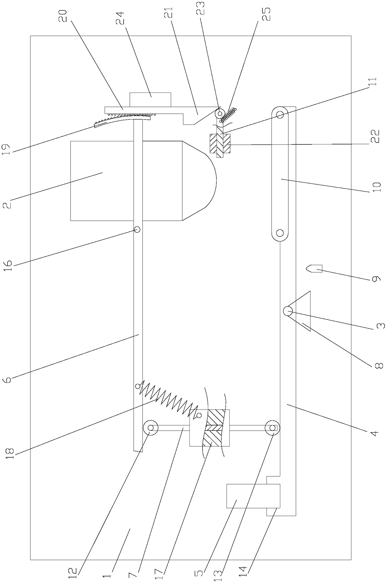
There are also many devices or equipment for distributing materials in the prior art, but these distributing materials devices or equipment have relatively large power and high energy consumption during the working process. The power needs to consume electric energy through the motor, and the equipment needs to use electric energy to distribute materials, and also to overcome the resistance or friction in the transmission process through electric energy, which will easily lead to high energy consumption, or waste of energy

Method used


Image

  • Distribution mechanism

Examples


Embodiment Construction

[0017] The present invention will be further described below in conjunction with the accompanying drawings and specific embodiments.

[0018] The material distributing mechanism of the present invention comprises a frame 1, which is provided with a barrel 2 for placing materials, and the frame 1 is rotatably connected with a swing rod 4 through a first hinge point 3, and one end of the swing rod 4 is provided with a counterweight 5 , the other end is provided with a belt transmission mechanism 10, and the belt transmission mechanism 10 is located below the barrel 2; the first hinge point 3 is used as the dividing point on the swing rod 4, and the end close to the counterweight 5 is the transmission area, that is, the swing rod in the figure The left end of 4; Near one end of belt drive mechanism 10 is the blanking area, that is, the right end of fork 4 in the figure; rotatably connected with cross bar 6 on frame 1, cross bar 6 is positioned at fork 4 top, and cross bar 6 is clo...


PUM


Abstract

The invention discloses a material distributing mechanism. The material distributing mechanism comprises a rack (1). The rack (1) is provided with a charging barrel (2) used for placing materials. The rack (1) is connected with an oscillating bar (4) in a rotating mode through a first hinged point (3). One end of the oscillating bar (4) is provided with a balancing weight (5), and the other end of the oscillating bar (4) is provided with a belt drive mechanism (10). The belt drive mechanism (10) is located below the charging barrel (2). By using the first hinged point (3) as a demarcation point, the end, close to the balancing weight (5), of the oscillating bar (4) is provided with a drive area, and the end, close to the belt drive mechanism (10), of the oscillating bar (4) is provided with a material falling area. The material distributing mechanism is lower in energy consumption and capable of fully utilizing the gravity of materials.

Description

technical field [0001] The invention relates to the technical field of material distribution, in particular to a material distribution mechanism. Background technique [0002] At present, in the process of industrialized continuous processing of materials, due to the needs of automatic processing technology, it is often necessary to continuously divide a granular material into several parts, and to ensure that the weights of each component are equal, that is, by One-point to multi-point distribution into the next process of processing. There are also many devices or equipment for distributing materials in the prior art, but these distributing materials devices or equipment have relatively high power and high energy consumption during the working process, which is due to the fact that the workpieces are driven during the distribution process. The power needs to consume electric energy through the motor, and the equipment needs to use electric energy to distribute materials, ...

Claims


Application Information

Patent Timeline
Patent Type & Authority Patents(China)
IPC IPC(8): B65B1/30B65G47/19B65G47/42
CPCB65B1/30B65G47/19B65G47/42
Inventor 冯幸国
Owner 浙江海重重工有限公司
Learn More