
Belt roll storage transport rack

A transport rack and belt technology, applied in the field of conveyor belt spare parts, can solve the problems of no storage device, large storage area, irregular storage of spare parts, etc., achieve simple structure, reduce floor space, and ensure the quality of spare parts Effect

Active Publication Date: 2020-06-12
LAIWU IRON & STEEL GRP
View PDF7 Cites 0 Cited by
  • Summary
  • Abstract
  • Description
  • Claims
  • Application Information

AI Technical Summary

Problems solved by technology

[0003] There is no special storage device for the belt rolls stored in the existing spare parts area, and for the convenience of unloading, the belt rolls are scattered in the storage area, resulting in a large storage area and irregular storage of spare parts. factor

Method used


Image

  • Belt roll storage transport rack
  • Belt roll storage transport rack
  • Belt roll storage transport rack

Examples


Embodiment 1

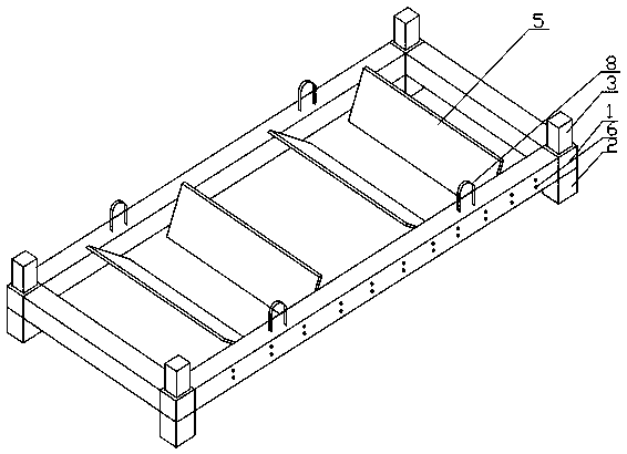
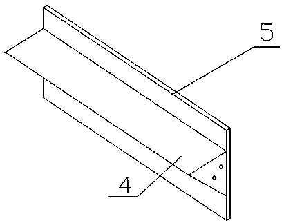
[0022] Example 1, such as figure 1 As shown, a belt roll storage transport frame includes: a bottom frame 1, a bracket cover 3 and a base 2 are respectively fixedly connected to the upper and lower parts of the four corners of the bottom frame 1, and the cross bars on both sides of the bottom frame 1 A plurality of positioning holes 6 are evenly distributed, and a plurality of support plates 4 are fixed by horizontal braces in the underframe 1, and the two ends of the support plates 4 are connected with the positioning holes 6 by bolts, as figure 2 As shown, each support plate 4 is fixedly connected with a sloping plate 5, and two adjacent sloping plates 5 are inclined in opposite directions.

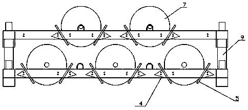
[0023] Such as image 3 As shown, this device can place the belt 7 in the air between two opposite inclined plates 5, and the chassis 1 itself can limit the belt roll 7. When the belt roll 7 is stored, it does not need to be bound and fixed. This device can place the belt Rolls, cabl...

Embodiment 2

[0027] Embodiment 2, based on the technical solution of Embodiment 1, as another embodiment, the present invention sets a plurality of bracket sleeves 3 and bases 2 on the upper and lower parts of each corner of the chassis 1, and sets The number is determined according to the weight of the load.

[0028] The bracket cover 3 , the base frame 1 and the base 2 are connected and fixed through a bracket 9 , and the bracket 9 is sleeved on the bracket cover 3 , passes through the base frame 1 , and is embedded in the base 2 . Support 9 plays the effect of connecting fixed support cover 3, underframe 1 and base 2, and this transportation frame can support and superimpose by support 9, and underframe 1 is increased, also can withdraw support 9 when there is no belt roll 7, will The bottom frames 1 are stacked together, which reduces the footprint of the transport frame.


PUM


Abstract

The invention relates to a belt coil storing and transporting frame. The frame comprises a bottom frame, wherein the upper parts and the lower parts of four corners of the bottom frame are fixedly connected with bracket sleeves and bases respectively; a plurality of positioning holes are uniformly distributed on cross rods on two sides of the bottom frame; a plurality of support plates are transversely supported and fixed in the bottom frame; two ends of the each support plate are in bolted connection with the positioning holes; each support plate is fixedly connected with an oblique plate; two adjacent oblique plate are tilted in opposite directions. The belt coil storing and transporting frame is simple in structure and convenient to assemble and disassemble; the storage space of the spare part area is effectively normalized; the occupied area is reduced; the operation efficiency, the safety and the firmness of storage and transportation of belt coils are improved; the quality of the spare parts is ensured; the operating efficiency is improved; the smooth progress of the production operation is ensured; the belt coil storing and transporting frame is suitable for popularization in the same industry.

Description

technical field [0001] The invention relates to the technical field of conveyor belt spare parts, in particular to a belt roll storage transport rack. Background technique [0002] In the metallurgical industry, belt conveyors are widely used as material transportation devices. The belt in the belt conveyor needs to be replaced regularly due to the influence of material wear and other factors. Belt rolls are used as spare parts. Due to the constraints of the production environment and site space, they cannot be stored near the production site of the transport aircraft, but are all stored in the spare parts area. [0003] There is no special storage device for the belt rolls stored in the existing spare parts area, and for the convenience of unloading, the belt rolls are scattered in the storage area, resulting in a large storage area and irregular storage of spare parts. factor. [0004] Therefore, how to make full use of the existing spare parts area, and how to store an...

Claims


Application Information

Patent Timeline
Patent Type & Authority Patents(China)
IPC IPC(8): B65D61/00B65D85/671
CPCB65D61/00B65D85/671
Inventor 程昊王中吕凤陈峰
Owner LAIWU IRON & STEEL GRP
Learn More