Closed conveyor

A conveyor and closed technology, which is applied in the direction of conveyor, conveyor objects, transportation and packaging, etc., can solve the problems of inability to realize airtight transportation and the inability to change the direction of transportation, and achieve high cleanliness requirements, strong adhesion, and reduced The effect of production costs

Inactive Publication Date: 2017-05-31
NANO PHARM TECH MACHINERY EQUIP
View PDF22 Cites 5 Cited by
  • Summary
  • Abstract
  • Description
  • Claims
  • Application Information

AI Technical Summary

Problems solved by technology

[0005] The purpose of the present invention is to solve the problem that the existing belt conveyor cannot realize airtight transportation and the transportation direction cannot be changed

Method used


Image

  • Closed conveyor
  • Closed conveyor
  • Closed conveyor

Examples


specific Embodiment approach 1

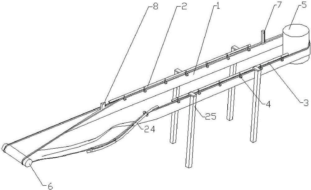
[0041] Specific implementation mode one: combine figure 1 and figure 2Describe this embodiment, a closed conveyor in this embodiment includes a conveyor belt 1, and also includes a left mounting frame 2, a right mounting frame 3, several transmission mechanisms 4, steering wheels 5, discharge rollers 6, and a feeding pipe 7. The left and right mounting frames are arranged in parallel. Several transmission mechanisms are fixedly installed under each mounting frame. Several transmission mechanisms are evenly distributed on the mounting frames where they are located. The steering wheels are located on the left and right mounting frames. The front of the conveyor belt and its axis are vertical, the unloading roller is located behind the left and right mounting frames and its axis is horizontal, the left and right sides of the conveyor belt are rolled up and tightly sealed to form a tubular or cylindrical shape, In order to be able to load the materials to be conveyed, when the p...

specific Embodiment approach 2

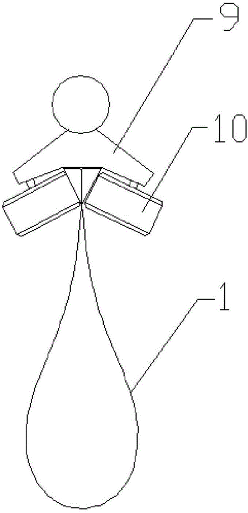
[0044] Specific implementation mode two: combination image 3 and Figure 4 Describe this embodiment, the transmission mechanism of this embodiment includes a connecting frame 9 and two rollers 10, the connecting frame is fixedly connected to the mounting frame where it is located, and the two rollers are installed on the connecting frame, the direction of rotation The same as the conveying direction of the conveyor belt, the installation method of the rollers on the connecting frame can adopt the following method: the two rollers are installed symmetrically on the left and right, and the axes of the two have an included angle and are from top to bottom from outside to inside Inclined, or the two rollers are installed symmetrically up and down, and the axes of the two are horizontal, or the two rollers are installed in a dislocation up and down, wherein the axis of the upper roller is vertical, and the axis of the lower roller is horizontal. There is a gap between the two rol...

specific Embodiment approach 3

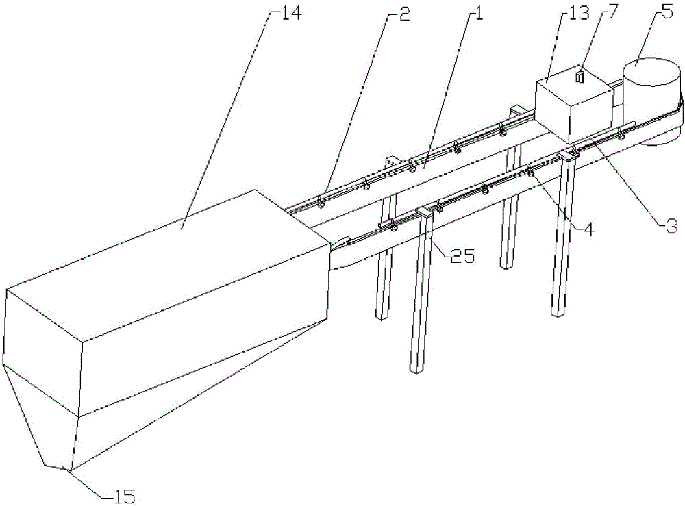
[0046] Specific implementation mode three: combination figure 1 Illustrate this embodiment, present embodiment also comprises feed box 13, the outlet of described feed pipe and the conveyor belt part that communicates with it are positioned at described feed box, described feed box is provided with for described conveyor belt and installation. The through hole through which the frame passes, and the inside of the feed box is in a negative pressure state. Of course, the steering wheel can also be located in the feed box. The setting of the feed box can ensure that when the material is conveyed to the conveyor belt (the connection between the conveyor belt and the feed pipe is in an open state), the material will not escape out of the feed box and cause pollution to the external environment. This embodiment is mainly applicable to materials to be transported that are prone to dust, strong adhesion, toxicity or irritating odor, etc. that are likely to pollute the environment. Ot...


PUM


Abstract

The invention discloses a closed conveyor, relates to a material conveyor, and aims to solve the problems of incapability of realizing closed conveying and incapability of changing the conveying direction in a traditional belt conveyor. Left and right mounting frames are arranged in parallel; left and right side edges of a conveying belt are upwards turned and tightly bonded to form a pipe shape or a cylinder shape; and after the conveying belt is matched and connected with a conveying mechanism on the right mounting frame in sequence, the conveying belt is bypassed through a steering wheel from right to left, then, is matched and connected with a conveying mechanism on the left mounting frame, is gradually unfolded to bypass through an unloading roller from top to bottom, and is overturned up and down to seal with the back end for butt joint to form a closed loop. The conveying belt is kept in a sealed state to realize closed material conveying; the conveying distance is changed through changing the lengths of the mounting frames and the conveying belt; and the direction of the conveying belt is changed through adding an auxiliary steering wheel and adjusting the extending directions of the mounting frames to realize turning conveying or high-height-fall conveying or even vertical conveying. The closed conveyor is used for material conveying.

Description

technical field [0001] The invention relates to a conveying device, in particular to a closed belt conveyor. Background technique [0002] At present, belt conveyors are used in various industries, and have the characteristics of strong conveying capacity, simple structure, easy maintenance, low cost, and strong versatility. However, it still has the following disadvantages, which affect its wide application: 1. The conveying method of the belt conveyor is open conveying, which cannot meet the requirements of easy dust generation, strong adhesion, toxicity, pungent smell, high cleanliness, Conveying requirements for materials that are easily polluted; 2. Belt conveyors are usually conveyed in a straight line, which cannot be applied to conveying conditions that require turning; 3. It is difficult for belt conveyors to achieve large height differences or climbing conveyance ; 4, the conveyor belt 1 is difficult to clean, especially when the conveyor belt 1 is long, the clean...

Claims


Application Information

Patent Timeline
Patent Type & Authority Applications(China)
IPC IPC(8): B65G21/02B65G15/00B65G47/34
CPCB65G15/00B65G21/02B65G47/34
Inventor 王孟刚
Owner NANO PHARM TECH MACHINERY EQUIP
Why Eureka
Try Eureka