A kind of back-section whole material device of belt conveyor
A belt conveyor and back section technology, which is applied in the field of the back section monolithic device of the belt conveyor, can solve the problems of low transportation efficiency and poor transportation environment in the back section, so as to improve the transportation efficiency, ensure the vibration effect, and enhance the compactness degree of effect
- Summary
- Abstract
- Description
- Claims
- Application Information
AI Technical Summary
Problems solved by technology
Method used
Image
Examples
Embodiment 1
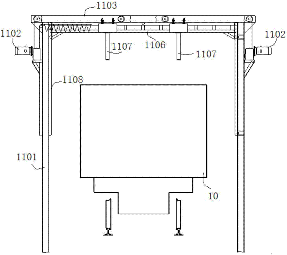
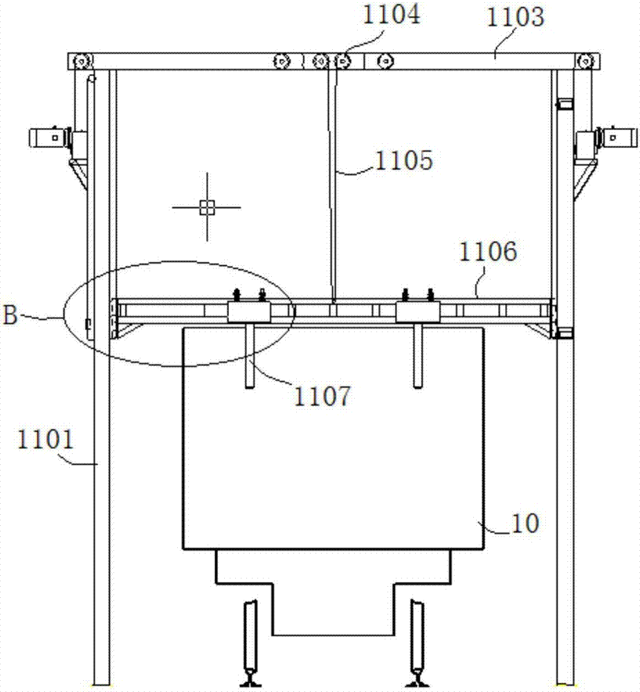
[0055] The rear-section whole-material device of a belt conveyor in this embodiment can compact the materials in the transport truck 10 alone, or it can be installed in the rear section of the belt conveyor to cooperate with it. This embodiment will aim at this The process of cooperating with the monolithic device and the belt conveyor will be described. Such as figure 1 As shown, the belt conveyor includes a frame 1, and the two ends of the frame 1 are respectively provided with a driving head wheel 2 and a driving tail wheel 3, and a conveyor belt 5 is covered and driven by the driving head wheel 2 and the driving tail wheel 3, Thus conveying the material to the unloading area.
[0056] The material is transported from the head end of the conveyor belt 5 to the tail end, and then naturally scattered to the material transport vehicle 10 below the conveyor belt 5 for subsequent transportation. The whole material device 12 first compacts and then flattens the bulk materials i...
Embodiment 2
[0069] The back-stage whole material device of a kind of belt conveyor of this embodiment is basically the same as Embodiment 1. Further, the cross section of the vibrating rod 1107 in this embodiment is shuttle-shaped, such as Figure 5 As shown, the shuttle-shaped design keeps the vibrating rod 1107 in a streamlined contact with the bulk material, effectively reducing the resistance between the vibrating rod 1107 and the bulk material in the driving state of the transport vehicle 10, and helping to improve the vibration of the vibrating rod 1107. Intensity; and the length of the vibrating rod 1107 is 1 / 5 to 1 / 3 of the depth of the carriage 10 of the transport truck, which can help reduce the contact between the vibrating rod 1107 and the bulk material while meeting the vibration requirements of the upper and middle bulk materials depth, thereby reducing the resistance between the two, and ensuring the vibration effect of the vibrating rod 1107.
Embodiment 3
[0071] This embodiment controls the lifting of the monolithic pressure roller by controlling the lifting of the lifting bracket, and uses the rolling effect of the monolithic pressure roller to realize the compaction and trimming of the material. Once the direction of the monolithic pressure roller is shifted or turbulent, It may cause accidental collision and impact on the material, causing the material to scatter. It may also cause the monolithic roller to be unable to evenly roll to the surface of the material due to serious deviation, and some materials may not be able to contact the monolithic roller, resulting in difficulty in guaranteeing the compaction effect. The design of the lifting bracket in this embodiment can effectively avoid the above problems.
[0072] The whole material device of the rear section of a belt conveyor in this embodiment is basically the same as in Embodiment 2. Further, the lifting bracket in this embodiment includes a frame structure composed o...
PUM
 Abstract
Description
Claims
Application Information
 - R&D Engineer
- R&D Manager
- IP Professional
- Industry Leading Data Capabilities
- Powerful AI technology
- Patent DNA Extraction
Browse by: Latest US Patents, China's latest patents, Technical Efficacy Thesaurus, Application Domain, Technology Topic, Popular Technical Reports.
© 2024 PatSnap. All rights reserved.Legal|Privacy policy|Modern Slavery Act Transparency Statement|Sitemap|About US| Contact US: help@patsnap.com


