Novel industrial glass pipe cutting device

A cutting equipment and industrial technology, applied in the field of new industrial glass tube cutting equipment, can solve the problems of time-consuming and laborious cutting process, injury to workers or equipment, damage to glass tubes, etc.

Active Publication Date: 2017-05-31
临泉县蓝天钢化玻璃有限公司
View PDF8 Cites 7 Cited by
  • Summary
  • Abstract
  • Description
  • Claims
  • Application Information

AI Technical Summary

Problems solved by technology

[0006] In order to overcome the disadvantages of the current glass tube cutting that may cause damage to the glass tube, cause injury to workers or equipment, and time-consuming and labor-intensive cutting process, the technical problem to be solved by the invention is to provide the possibility of causing damage to the glass tube during cutting A new type of industrial glass tube cutting equipment that is small, causes less injury to workers or equipment, and saves time and effort during the cutting process

Method used


Image

  • Novel industrial glass pipe cutting device
  • Novel industrial glass pipe cutting device
  • Novel industrial glass pipe cutting device

Examples


Embodiment 1

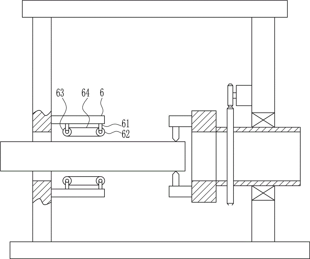
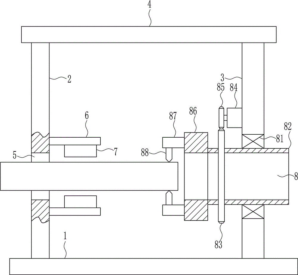
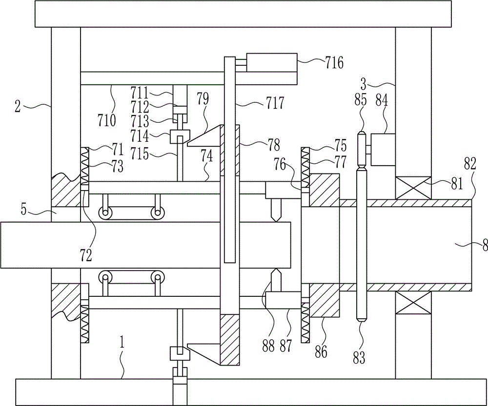
[0030] A new type of industrial glass tube cutting equipment, such as Figure 1-3 As shown, it includes a bottom plate 1, a left support plate 2, a right support plate 3, a top plate 4, a fixed plate 6, a rubber block 7 and a cutting device 8. The left support plate 2 is installed on the left side of the bottom plate 1 by welding, and the bottom plate The upper right side of 1 is installed with the right support plate 3 by means of welding, the upper ends of the left support plate 2 and the right support plate 3 are installed with the top plate 4 by welding, the lower side of the left support plate 2 has a through hole 5, and the left support plate 2 The fixed plate 6 is symmetrically installed on the right side by means of bolt connection, and the center position between the two fixed plates 6 is on the same level as the position of the through hole 5. The inner side of the fixed rod is installed with a rubber block 7 by means of bolt connection. A cutting device 8 is install...


PUM


Abstract

The invention relates to a glass cutting device, in particular to a novel industrial glass pipe cutting device. The invention aims to solve the technical problem so as to provide the novel industrial glass pipe cutting device, which has less possibilities on damaging glass pipes and hurting workers or equipment when being used for cutting the glass pipes, and is time and labor saving during a cutting process. In order to solve the technical problem, the invention provides the novel industrial glass pipe cutting device, which comprises a bottom plate and the like, wherein a left support plate is arranged at the left side above the bottom plate in a welding way; a right support plate is arranged at the right side above the bottom plate in a welding way; a top plate is arranged on the upper ends of the left support plate and the right support plate through a welding way; a through hole is formed in the lower side of the left support plate; fixing plates are symmetrically arranged at the right side of the left support plate through a bolt connection way. The novel industrial glass pipe cutting device provided by the invention achieves the effects that the possibilities on damaging the glass pipes and hurting the workers or the equipment when being used for cutting the glass pipes are less, and the time and the labor are saved during the cutting process.

Description

technical field [0001] The invention relates to a glass cutting device, in particular to a novel industrial glass tube cutting device. Background technique [0002] Glass is a transparent solid at room temperature. It forms a continuous network structure when it melts. It is a silicate non-metallic material that gradually increases in viscosity and hardens during cooling. The chemical composition of ordinary glass is Na2O·CaO·6SiO2, and the main component is silicon dioxide. Widely used in buildings, used for wind and light transmission, belongs to the mixture. There are also colored glass that is mixed with certain metal oxides or salts to show color, and tempered glass made by a special method. Sometimes some transparent plastics (such as polymethyl methacrylate) are also called plexiglass. [0003] At present, when cutting the glass tube, most of them are cut with the grinding wheel of the equipment, or manually. The use of the grinding wheel to cut the glass tube will...

Claims


Application Information

Patent Timeline
Patent Type & Authority Applications(China)
IPC IPC(8): C03B33/06
CPCC03B33/06
Inventor 不公告发明人
Owner 临泉县蓝天钢化玻璃有限公司
Why Eureka
Try Eureka