Continuous production line for flexible galvanized steel pipe

A galvanized steel pipe and production line technology, applied in hot-dip plating process, coating, metal material coating process and other directions, can solve the problems of inability to achieve continuous operation, low efficiency of manual hanging plating, large difference in product quality, etc. The effect of continuous production of high quality, reduced damage and stable equipment operation

Active Publication Date: 2017-05-31
山东鲁盟威金属科技有限公司
View PDF4 Cites 7 Cited by
  • Summary
  • Abstract
  • Description
  • Claims
  • Application Information

AI Technical Summary

Problems solved by technology

[0002] Hot-dip galvanized steel pipes are widely used in construction, life, and roads. At present, the production method mainly uses a spreader to immerse the steel pipes in the zinc solution, and then extracts and then treats the inner wall of the surface. This kind of manual hanging plating is low in efficiency and labor-intensive. , and operators are prone to burn accidents in this harsh working environment. As galvanized steel pipes are more and more widely used, their demand is increasing. The traditional way of galvanizing steel pipes has been unable to meet market demand. , in order to increase its output, some semi-automatic devices and tooling gradually appeared
[0003] Through the use of the above-mentioned automatic galvanized steel pipe equipment, it is found that the current galvanizing method still uses a spreader. It is necessary to galvanize a batch of steel pipes before galvanizing the next batch of steel pipes. Although the change from zinc to large-scale galvanizing has improved, due to the large quality difference between products, there are too many human factors, which leads to defects in its surface quality, and after the production of a batch of steel pipes, it is necessary to wait for the next batch Steel pipes cannot achieve continuous operation

Method used


Image

  • Continuous production line for flexible galvanized steel pipe
  • Continuous production line for flexible galvanized steel pipe

Examples


Embodiment Construction

[0025] In order to facilitate the understanding of those skilled in the art, the present invention will be further described below in conjunction with the accompanying drawings.

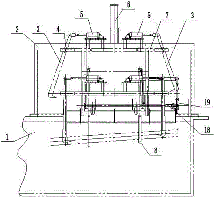
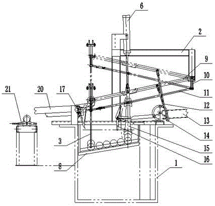
[0026] Such as figure 1 As shown, a production line for continuous production of flexible galvanized steel pipes includes a zinc pot 1 and a main support 2, the zinc pot is arranged under the main support 2, zinc liquid is stored in the zinc pot 1, and the main support 2 includes Feeding mechanism, depressing mechanism, lifting mechanism, dialing mechanism and conveying mechanism, the feeding mechanism and depressing mechanism transmit the steel pipe into the zinc liquid in the zinc pot 1, and the lifting mechanism extracts the zinc liquid in the zinc pot 1 , the pull-out mechanism transports the galvanized steel pipe to the transmission mechanism, the depressing mechanism connects the feeding mechanism, the lifting mechanism and the pull-out mechanism through a four-bar linkage, and the transmission...


PUM


Abstract

The invention discloses a continuous production line for a flexible galvanized steel pipe, and belongs to the technical field of hot-galvanizing automatic production. The continuous production line comprises a zinc pot and a main support, wherein the zinc pot is arranged below the main support; liquid zinc is stored in the zinc pot; the main support comprises a feeding mechanism, a downward pressing mechanism, a lifting mechanism, a poking mechanism and a delivery mechanism; the feeding mechanism and the downward pressing mechanism convey steel pipes into liquid zinc in the zinc pot; the lifting mechanism extracts liquid zinc from the zinc pot; the poking mechanism conveys galvanized steel pipes to the delivery mechanism; the downward pressing mechanism enables the feeding mechanism, the lifting mechanism and the poking mechanism to be connected through a four-bar mechanism; the delivery mechanism is arranged in the rear of the poking mechanism. The adopted automatic production line can realize continuous production of galvanized steel pipes, improve the surface quality and liberate the labor force, and can be applied to steel pipes with different pipe diameters.

Description

technical field [0001] The invention relates to the technical field of hot-dip galvanizing automatic production, in particular to a production line for continuous production of flexible galvanized steel pipes. Background technique [0002] Hot-dip galvanized steel pipes are widely used in construction, life, and roads. At present, the production method mainly uses a spreader to immerse the steel pipes in the zinc solution, and then extracts and then treats the inner wall of the surface. This kind of manual hanging plating is low in efficiency and labor-intensive. , and operators are prone to burn accidents in this harsh working environment. As galvanized steel pipes are more and more widely used, their demand is increasing. The traditional way of galvanizing steel pipes has been unable to meet market demand. In order to increase its output, some semi-automatic devices and tooling gradually appeared. [0003] Through the use of the above-mentioned automatic galvanized steel ...

Claims


Application Information

Patent Timeline
Patent Type & Authority Applications(China)
IPC IPC(8): C23C2/06C23C2/38
CPCC23C2/003C23C2/06C23C2/38
Inventor 李培芹
Owner 山东鲁盟威金属科技有限公司
Why Eureka
Try Eureka