
Integral lowering and demolition method for continuous beam bridge

A bridge pier and integral technology, which is applied in the field of demolition of the entire continuous girder bridge, can solve the problems of high cutting costs, unknown beam section bearing capacity, unfavorable production saving, etc.

Inactive Publication Date: 2017-05-31
CCCC ROAD & BRIDGE SPECIAL ENG
View PDF7 Cites 21 Cited by
  • Summary
  • Abstract
  • Description
  • Claims
  • Application Information

AI Technical Summary

Problems solved by technology

The common method is to cut the abandoned bridge into small pieces and then lower it down, which will cause high cutting costs and is not conducive to saving production; in addition, in order to improve economic benefits, the concrete bridge is cut into larger demolition units, forming a whole span Technology, the existing patented technology, the two Chinese patents with patent No. 201510042199.9 and patent No. 201510063144.6 proposed a method of dismantling the entire span bridge with different support systems, but this method needs to cut off the prestress of the continuous box girder, changing the original Structural force system, the bearing capacity of the beam section is unknown, and some beam sections need to be strengthened and then lowered.

Method used


Image

  • Integral lowering and demolition method for continuous beam bridge

Examples


Embodiment Construction

[0029] The preferred embodiments of the present invention are given below in conjunction with the accompanying drawings to describe the technical solution of the present invention in detail.

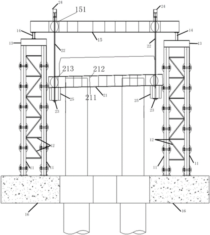
[0030] The method for lowering and dismantling the entire continuous girder bridge of the present invention comprises the following steps:

[0031] Step 1. Preparation;

[0032] Step 2. Remove the temporary pier system for the whole bridge and install it, which is used for the calculation and design of the temporary pier system for reasonable structural force calculation and design, so as to meet the weight of the main girder of the whole bridge;

[0033] Step 3. Install temporary buttresses and cut the flange of the main girder; design and calculate according to the force characteristics of the entire bridge structure, set up temporary buttresses and temporary buttress connection foundations. abutments or enlarged caps to form a whole to prevent uneven subsidence and deformation of the...


PUM


Abstract

The invention discloses an integral lowering and demolition method for a continuous beam bridge. The method adopts a pier system module and a lowering system module and includes steps: step one, preparing; step two, mounting an integral demolition temporary pier system; step three, mounting temporary piers and cutting main beam flanges; step four, mounting a integral lowering system; step five, synchronously lowering, lifting, constructing and the like. The pier system module comprises steel pipe piles, temporary pier parallel connectors, transverse connection beams, longitudinal distribution beams and the like. The lowering system module comprises dragging beams, a steel stranded lifting rope anchor system, anchor plates, continuous lifting jacks and supporting blocks. The method is applicable to demolition of the high-pier continuous beam bridge large in clearance of span and has advantages of quickness in demolition, safety in construction and cost saving.

Description

technical field [0001] The invention relates to a method for dismantling a girder bridge, in particular to a method for dismantling a whole continuous girder bridge. Background technique [0002] Since the 1970s, concrete continuous box girder bridges have become the most competitive bridge type within the range of 60m to 300m due to their good adaptability and economy. They have been widely used in my country, and tens of thousands of them have been built. Among concrete bridges, continuous girder bridges are more widely used. During the use of these bridges, some bridges need to be demolished due to congenital design defects, changes in use functions, or road network re-planning. Bridges that are not subject to boundary conditions can be demolished by blasting, but for densely populated and nearby buildings Continuous girder bridges such as deep-water river-crossing bridges and river-crossing bridges that cannot be demolished by blasting need to find an efficient, environm...

Claims


Application Information

Patent Timeline
Patent Type & Authority Applications(China)
IPC IPC(8): E01D24/00
CPCE01D22/00
Inventor 朱慈祥陈亮马小云王蔚盛海军李少芳周华威刘昂罗松高望
Owner CCCC ROAD & BRIDGE SPECIAL ENG
Learn More