Sinking vertical lifting gate

A vertical lift and gate technology, applied in the field of gates, can solve the problems of large capacity of hydraulic hoists, water blocking of the gate body, increased load, etc., so as to improve reliability and safety, avoid water blocking and garbage jam, and reduce installation. the effect of difficulty

Inactive Publication Date: 2017-05-31
浙江衢州河口闸门有限公司
View PDF5 Cites 8 Cited by
  • Summary
  • Abstract
  • Description
  • Claims
  • Application Information

AI Technical Summary

Problems solved by technology

The hydraulic flap gate has the following defects: after the gate is fully opened, the gate body lies horizontally in the water body of the river channel, and the gate body has a serious water blocking phenomenon, and the lying gate body is easy to block floating objects (garbage jams) problem), resulting in an increase in the load. In severe cases, when an object hits the gate, the flap gate will be washed away, and the reliability cannot be guaranteed, so it cannot meet the needs of use.
The operation of the gate is to rotate around the hinge seat at the bottom. When it is fully opened, it can lie flat on the gate floor. Generally, the horizontal gate is operated by a hydraulic hoist or hoist hoist, which is difficult to meet the requirements for large-span water retention. Hydraulic lift dams The structure of the door body is thin, the inspection and maintenance conditions of the moving parts of the door body and the water seal are poor, and the hydraulic cylinder is in long-term work, and the capacity of the hydraulic hoist is large, and the synchronization of the hydraulic system is highly required, otherwise the gate will be seriously damaged

Method used


Image

  • Sinking vertical lifting gate
  • Sinking vertical lifting gate
  • Sinking vertical lifting gate

Examples


Embodiment Construction

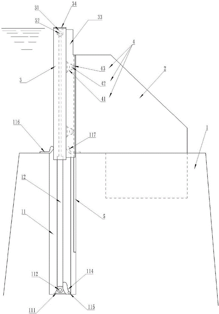
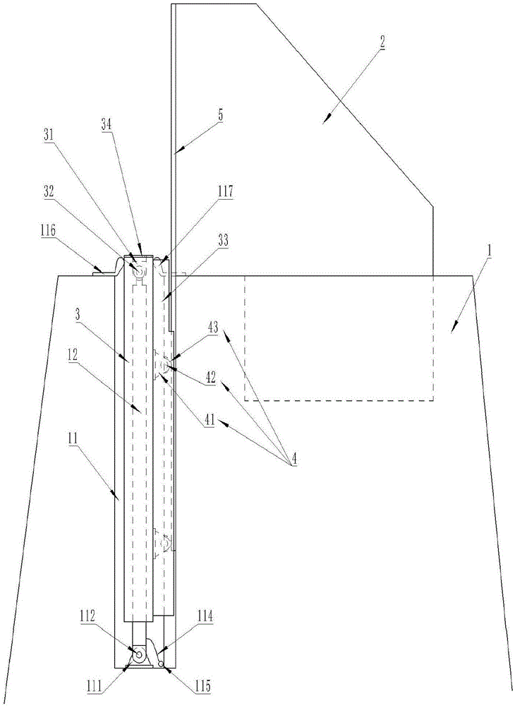
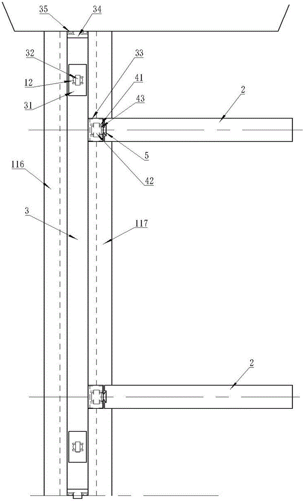
[0024] like figure 1 , figure 2 and image 3 As shown, a sunken vertical lift gate includes a dam body 1 on the river channel, two buttresses 2 are fixedly arranged on the weir dam body 1, and a gate leaf 3 is installed on the front edge of the buttress 2, and the two A door slot 11 is arranged on the weir dam body 1 facing the water of each pier 2, and two fixed oil cylinder seats 111 are installed on the bottom of the door slot 11 below each door leaf 3, and oil cylinder shafts are installed on the fixed oil cylinder seats 111. One 112; a movable cylinder seat 31 is arranged on the inner wall of the upper end surface of the door leaf 3 at the vertical corresponding position to the fixed oil cylinder seat 111, and the movable oil cylinder seat 31 is connected with the oil cylinder shaft 2 32, and the oil cylinder shaft 2 32 and the oil cylinder shaft 112 pass through the hydraulic cylinder 12 The hydraulic cylinder 12 is connected to the external hydraulic control system t...


PUM


Abstract

The invention discloses a sinking vertical lifting gate. The sinking vertical lifting gate includes a weir body arranged on a river channel, support piers, and gate leaves; a gate groove is each formed in the weir body of upstream surfaces of the two support piers; two fixing oil cylinder seats are arranged on the bottom of the corresponding gate groove under each door leaf; first oil cylinder shafts are arranged on the fixing oil cylinder seats; movable oil cylinder seats are arranged on inner walls of the upper end surfaces of the door leaves at corresponding positions perpendicular to the fixing oil cylinder seats; second oil cylinder shafts are connected to the movable oil cylinder seats; the second oil cylinder shafts are connected to the first oil cylinder shafts through hydraulic oil cylinders; rail casings are vertically arranged on downstream surfaces of the gate leaves; at least two rolling members are arranged in each rail casing; the rolling members match slide rails; the upper parts of the slide rails are arranged on the upstream surfaces of the support piers, and the lower parts of the slide rails are arranged on inner walls of the gate grooves; and the hydraulic oil cylinders are connected to an external hydraulic control system through oil tubes. The sinking vertical lifting gate can avoid water blocking and trash blocking, can reduce the cost, and can meet the use demand of people.

Description

technical field [0001] The invention relates to the technical field of gates, in particular to a sunken vertical lift gate. Background technique [0002] It is known that a gate is a control facility for closing and opening a water channel, which is an important part of a hydraulic structure and can be used to intercept, control water flow, control water level, regulate flow, discharge sediment and floating objects, etc. [0003] The gate types of existing gates are as follows: steel dam gates, hydraulic flap gates, hydraulic lifting dams and pneumatic shield gates, and steel dam gates, hydraulic flap gates and hydraulic lifting dams are used more. [0004] Steel Dam Gate—Steel Dam Gate is a new type of adjustable overflow gate in China in recent years, which is suitable for long-span and low water head conditions. The steel dam gate is also called the bottom shaft driven flap gate. The gate is composed of door leaf, fixed bottom shaft, hinge seat, crank arm, wall penetrati...

Claims


Application Information

Patent Timeline
Patent Type & Authority Applications(China)
IPC IPC(8): E02B7/26E02B7/36E02B7/54
CPCE02B7/26E02B7/36E02B7/54
Inventor 张晓敏张晓峰
Owner 浙江衢州河口闸门有限公司
Why Eureka
Try Eureka