
Calculating method for long-and-short pile combined support structure

A support structure and calculation method technology, which is applied in calculation, infrastructure engineering, excavation, etc., can solve the problems of wasting resources, increasing the cost of foundation pit support, etc., and achieves the goal of strong pertinence, good versatility, and wide application range Effect

Active Publication Date: 2017-05-31
WUHAN SURVEYING GEOTECHN RES INST OF MCC
View PDF7 Cites 4 Cited by
  • Summary
  • Abstract
  • Description
  • Claims
  • Application Information

AI Technical Summary

Problems solved by technology

The resulting result is: for foundation pits of medium depth with an excavation depth of about 7-10m, the length of the supporting piles is more than 20m, or even more than 30 meters, which greatly increases the cost of foundation pit support and is extremely wasteful. The resources of the country and society run counter to the concept of low-carbon environmental protection advocated by the whole society today

Method used


Image

  • Calculating method for long-and-short pile combined support structure
  • Calculating method for long-and-short pile combined support structure
  • Calculating method for long-and-short pile combined support structure

Examples


Embodiment Construction

[0028] In order to make the above objects, features and advantages of the present invention more comprehensible, specific implementations of the present invention will be described in detail below in conjunction with the accompanying drawings.

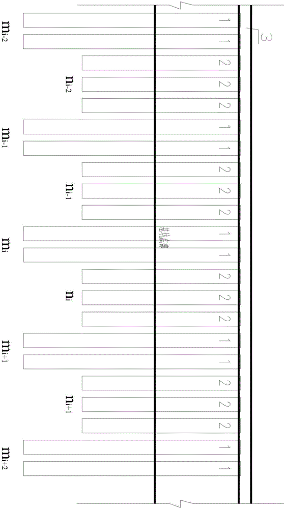
[0029] according to figure 1 , figure 2 As shown, a calculation method for the combined support structure of long and short piles, several long-supported pile areas and short-supported pile areas are arranged at intervals along the foundation pit wall, and each long-supported pile area is composed of two long-supported piles 1 Each short-support pile area is composed of three short-support piles 2, and the pile tops of the long-support pile 1 and the short-support pile 2 are connected by a crown beam 3;

[0030] choose figure 1 The 8 supporting piles in the middle line frame are used as the weakest and dangerous local unit model for analysis and calculation. The earth pressure above the pile bottom of the short supporting pile 2 is ...


PUM


Abstract

The invention provides a calculating method for a long-and-short pile combined support structure. When the long-and-short pile combined support structure is designed, for a local unit model which is located at the selected weakest and most dangerous section and contains N piles, the soil pressure at the part above the pile bottoms of short support piles is jointly borne by long support piles and the short support piles, and the soil pressure at the part below the pile bottoms of the short support piles is completely borne by the long support piles independently; 2N boundary conditions are formed by presuming that the bending moment and shearing force at the pile bottom of each pile are zero, N boundary conditions are formed by presuming that the bending moment at the pile top of each pile is zero, N<p-1> boundary conditions are formed by presuming that the pile topes of all the piles are equal in displacement, one boundary condition is formed by presuming that top beams in the local unit model are in a balanced state, and then all the boundary conditions are combined to form 4N boundary conditions; and a local unit model control equation set based on the elastic resistance method theory is solved through a shooting algorithm based on the Broyden method iteration, and thus the displacement, rotating angle, bending moment and shearing force of a pile body of each support pile are obtained. According to the calculating method, the concept of the local unit model is provided, and only the most dangerous area needs to be calculated; the design safety is achieved, and meanwhile, the spatial effect of the combined action of the long-and-short pile combined structure can be considered, so that the physical concept is clear, and calculation is simple; and the shooting algorithm based on the Broyden method iteration is not sensitive to the setting of an initial value, the convergence speed is high, and the stability is good.

Description

technical field [0001] The invention relates to the technical field of deep foundation pit support engineering, in particular to a calculation method for a combined support structure of long and short piles. Background technique [0002] In the design process of foundation pit support in deep soft soil areas, in order to ensure the overall anti-slip stability, anti-uplift stability and anti-overturning stability of the foundation pit, the foundation pit support piles need to pass through the deep soft soil to enter the underlying performance. In better strata, the pile length of the supporting pile is mainly determined by the burial depth of the stable stratum under the soft soil layer, and has little relationship with the excavation depth of the foundation pit. In this case, when the excavation depth of the foundation pit is deepened , the support design generally only needs to adjust the pile diameter of the support pile, the reinforcement of the pile body and the number o...

Claims


Application Information

Patent Timeline
IPC IPC(8): E02D17/04G06F17/50
CPCE02D17/04G06F30/13
Inventor 陈斌丁洪元昌钰宁国立刘耀峰肖玉成潘献义叶坤黄静
Owner WUHAN SURVEYING GEOTECHN RES INST OF MCC
Learn More