Rotational flowcleaner

A technology of scale remover and transmission shaft, which is applied to cleaning appliances, wellbore/well components, earth-moving drilling, etc., can solve the problems of affecting water injection operation, high labor intensity and high cost, and achieves good descaling effect and labor intensity. Small, low cost effect

Pending Publication Date: 2017-05-31
DONGHAO MECHANICAL & ELECTRONICS
View PDF20 Cites 0 Cited by
  • Summary
  • Abstract
  • Description
  • Claims
  • Application Information

AI Technical Summary

Problems solved by technology

Chemical descaling will cause damage to downhole tubing and tools, and the cost is high; while mechanical descaling requires single-well operation to pull out the tubing, which affects water injection operations, and is time-consuming, labor-intensive, and costly

Method used


Image

  • Rotational flowcleaner

Examples


Embodiment Construction

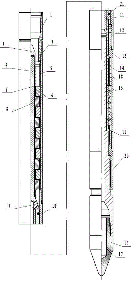
[0015] The cyclone descaler includes a turbine 8 motor, a transmission shaft assembly and a nozzle 16, the lower end of the turbine 8 motor is connected to the transmission shaft assembly, the lower end of the transmission shaft assembly is connected to the nozzle 16, and the nozzle 16 includes a water outlet.

[0016] The turbine 8 motor includes an upper joint 1, the lower outer wall of the upper joint 1 is connected to the outer cylinder 2, the lower end of the outer cylinder 2 is connected to the lower joint 10 of the outer cylinder, the lower end of the lower joint 10 of the outer cylinder is connected to the transmission shell 13, and the outer cylinder 2 is provided with a mandrel 4, the core The upper end of the shaft 4 is provided with a diversion cone 3, the lower end of the diversion cone 3 is connected to the bushing 7, the lower end of the bushing 7 is connected to the turbine 8, the bearing bush 5 is arranged between the mandrel 4 and the outer cylinder 2, the guid...


PUM


Abstract

The invention relates to the technical field of oil casing washing, in particular to a rotational flowcleaner. The rotational flowcleaner comprises a turbine motor, a drive shaft assembly and a sprayer, the lower end of the turbine motor is connected to the drive shaft assembly, and the lower end of the drive shaft assembly is connected to the sprayer; the turbine motor comprises an upper contact, the outer wall of the lower portion of the upper contact is connected to an outer canister, the lower end of the outer canister is connected to a lower contact of the outer canister, the lower end of the lower contact of the outer canister is connected to the drive shaft assembly, the outer canister is internally provided with a core shaft, the upper end of the core shaft is provided with a stream guidance cone, a bearing bush is arranged between the core shaft and the outer canister, the lower portion of the bearing bush is provided with a guide wheel, the upper and lower ends of the guide wheel are connected to the bearing bush and the lower contact of the outer canister in an inserting mode respectively, the outer wall of the core shaft is sleeved with a turbine, the lower portion of the core shaft is provided with a flushing port, the flushing port is located at the lower portion of the turbine, and the lower end of the core shaft is connected to the drive shaft assembly through a lower contact of the core shaft. The rotational flowcleaner is simple in structure, during oil casing washing, an oil outlet pipe does not need lifting, the labor intensity is low, the required time is short, the cleaning speed is high, the cleaning effect is good, and the cost is low.

Description

technical field [0001] The invention relates to the technical field of oil casing cleaning, in particular to a cyclone descaler. Background technique [0002] Scaling is unavoidable in the oil and gas production process of oil wells, and the insoluble mixture is gradually mixed together and adhered to the drilling equipment and pipelines, making the surface of the production tubing rough, increasing the frictional resistance, reducing the flow rate, and even reducing the flow cross-sectional area of ​​the tubing. become smaller, so that the production efficiency is greatly reduced. There are two commonly used descaling methods at present, chemical descaling and mechanical descaling. Chemical descaling will cause damage to downhole tubing and tools, and the cost is high; while mechanical descaling requires single-well operation to pull out the tubing, which affects water injection operations, and is time-consuming, labor-intensive, and costly. Contents of the invention ...

Claims


Application Information

Patent Timeline
Patent Type & Authority Applications(China)
IPC IPC(8): E21B37/00
CPCE21B37/00
Inventor 苗长山董应祥张永亚云飞郭连会
Owner DONGHAO MECHANICAL & ELECTRONICS
Why Eureka
Try Eureka