Novel vertical shaft heading machine and construction method thereof

A technology for roadheaders and shafts, which is applied to shaft equipment, sinking, and earthwork drilling and mining. It can solve problems such as inability to complete excavation at one time, low drilling efficiency, and construction impact, so as to improve overall construction efficiency and reduce downhole construction. The number of personnel and the effect of saving construction costs

Active Publication Date: 2017-05-31
CHINA RAILWAY ENGINEERING EQUIPMENT GROUP CO LTD
View PDF7 Cites 17 Cited by
  • Summary
  • Abstract
  • Description
  • Claims
  • Application Information

AI Technical Summary

Problems solved by technology

The main equipment of the ordinary drilling method includes rock drilling, rock grabbing machine, hanging plate and other equipment. The drilling and blasting method is used to excavate the shaft, which has complicated construction technology, low efficiency, low safety factor of workers and high labor intensity; the drilling method mainly The equipment is shaft drilling rig, which adopts pressurized drilling, and the drilling efficiency is low. For example, some drilling tools have very low excavation efficiency when encountering hard rock and other strata. Large vertical shafts must be excavated and reamed, and the excavation cannot be completed at one time. After the drill pipe breaks, it is trou

Method used


Image

  • Novel vertical shaft heading machine and construction method thereof
  • Novel vertical shaft heading machine and construction method thereof
  • Novel vertical shaft heading machine and construction method thereof

Examples


Embodiment Construction

[0027] The specific implementation manners of the present invention will be described in detail below in conjunction with the accompanying drawings.

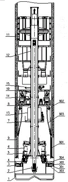
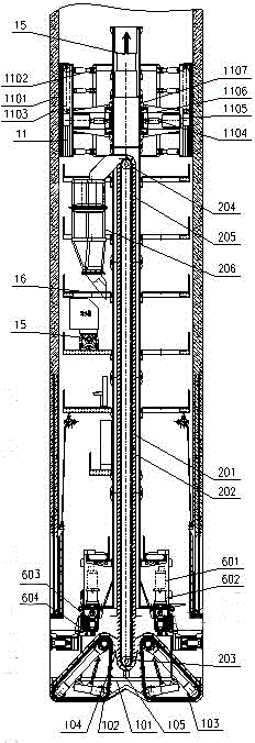
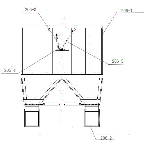
[0028] see figure 1 , figure 2 , image 3 , Figure 4 and Figure 5, serial number in the figure: 1 is the cutter head, 2 is the slag discharge device, 3 is the stabilizer, 4 is the one-story platform, 5 is the support platform, 6 is the main driving device, 7 is the second-story platform, 8 is the three-story platform , 9 is the shaft wall construction device, 10 is the four-story platform, 11 is the shoe propulsion device, 12 is the column, 13 is the control system, 14 is the hydraulic system, 15 is the ventilation and drainage system, 16 is the auxiliary construction system, 101 is the knife Disk main body, 102 is cutter, 103 is slag cleaning device, 104 is slag collecting device, 105 is swivel joint, 103-1 is scraper, 103-2 is scraper chain, 103-3 is reversing wheel, 103-4 103-5 is the driving wheel, 103-6 is the main ...


PUM


Abstract

The invention relates to the technical field of vertical shaft constructing, in particular to a novel vertical shaft heading machine. The novel vertical shaft heading machine comprises a stand column, a cutter disc, a main driving unit, a plurality of stabilizers, a first-layer platform, supporting platforms, a second-layer platform, a third-layer platform, a fourth-layer platform, a boot-supporting advancing unit and a slag discharging unit, wherein the stand column is arranged to be coaxial with a vertical shaft, the vertical shaft is arranged at the lower end of the stand column, the main driving unit is installed between the cutter disc and the stand column, the multiple stabilizers are installed around the lower end of the main driving unit, the first-layer platform is installed above the multiple stabilizers, the supporting platforms are upwards fixedly installed around the stand column in sequence, and the slag discharging unit is perpendicularly installed in the middle of the stand column; and the cutter disc is fixedly connected with the output end of the main driving unit. According to the novel vertical shaft heading machine, through mechanical excavation, disturbance of blasting on the stratum is reduced, meanwhile the mechanical excavation can improve the shaft wall construction quality, and the construction quantities of over-excavation and under-excavation are reduced; construction cost is reduced, devices are highly integrated, and after excavating is conducted, supporting closely follows; and the side gap is small, the shaft wall is supported in time, construction safety can be ensured, and simultaneously the slag discharging unit is designed.

Description

technical field [0001] The invention relates to the technical field of shaft construction, in particular to a novel shaft boring machine and a construction method thereof. Background technique [0002] At present, blind well construction technologies mainly include common sinking method and drilling method. The main equipment of the ordinary drilling method includes rock drilling, rock grabbing machine, hanging plate and other equipment. The drilling and blasting method is used to excavate the shaft, which has complicated construction technology, low efficiency, low safety factor of workers and high labor intensity; the drilling method mainly The equipment is shaft drilling rig, which adopts pressurized drilling, and the drilling efficiency is low. For example, some drilling tools have very low excavation efficiency when encountering hard rock and other strata. Larger vertical shafts must be excavated and reamed, and the excavation cannot be completed at one time. After the...

Claims


Application Information

Patent Timeline
IPC IPC(8): E21D1/03
CPCE21D1/03
Inventor 李建斌肖威杨聚辉吕旦周倩史伟闫扬义冯琳
Owner CHINA RAILWAY ENGINEERING EQUIPMENT GROUP CO LTD
Why Eureka
Try Eureka