Grouting structure in tunnel driving process and grouting method matched with grouting structure

A technology of tunnel excavation and grouting, which is used in tunnels, tunnel linings, and earth-moving drilling and mining, etc., can solve the problem of inability to fill the back gap of segments, and achieve easy maintenance and post-maintenance, high slurry utilization, and simple equipment structure. Effect

Active Publication Date: 2017-05-31
CHINA RAILWAY TUNNEL GROUP CO LTD +1
View PDF7 Cites 11 Cited by
  • Summary
  • Abstract
  • Description
  • Claims
  • Application Information

AI Technical Summary

Problems solved by technology

[0005] The purpose of the present invention is to solve the problem in the prior art that synchronous grouting cannot fill the segment back gap, and to provide a grouting structure for solving the back gap in the tunnel excavation process

Method used


Image

  • Grouting structure in tunnel driving process and grouting method matched with grouting structure
  • Grouting structure in tunnel driving process and grouting method matched with grouting structure
  • Grouting structure in tunnel driving process and grouting method matched with grouting structure

Examples


Embodiment 1

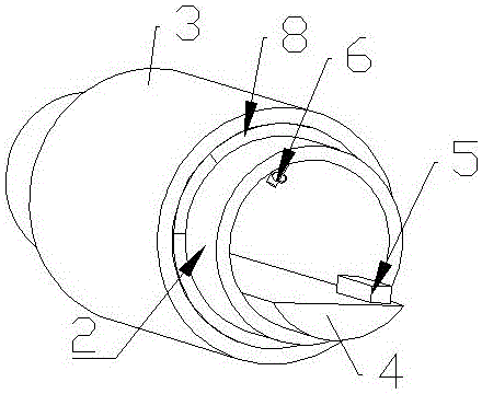
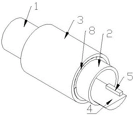
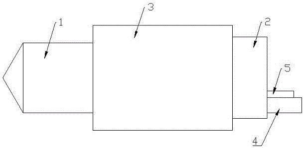
[0031] Embodiment 1: A kind of grouting structure in tunnel excavation process, see Figure 1 to Figure 4 , starting from the inner wall of the tunnel, including rock formations and pipe layers inwards to form side arches with joints as units; support frames are provided between pipe layers and rock layers to form hollow interlayers; bottom lining is provided at the bottom of side arches On the platform, grouting reserved holes connecting the hollow interlayer are provided at the top and bottom of the segment layer of each side arch. The grouting reserved holes are movably connected to the grouting pipeline, and the other end of the pipeline is connected to the grouting machine.

[0032] One or two grouting reserved holes are arranged symmetrically on the top of the segment layer of each top arch, and the height of the grouting reserved holes is higher than 0.93 of the total height of the tunnel.

[0033] A feeding valve is provided on the grouting pipeline.

[0034] The grou...

Embodiment 2

[0057] Embodiment 2: The method and principle of this embodiment are the same as in Embodiment 1, and the specific difference is that: the mortar is fully stirred with water glass at 20:1, and 1000 ml of mortar and 50 ml of pure water glass are used in a measuring cup, and they are fully stirred in the bucket, and the two The initial setting time of each test was greater than 5 minutes.

Embodiment 3

[0058] Embodiment 3: the method and principle of this embodiment are the same as in embodiment 1, the specific difference is: the mortar is fully stirred with water glass at 5:1, use a measuring cup to get 1000ml of mortar, 200ml of pure water glass, add to the bucket and fully stir, two The initial setting time of the first test is about 60s.


PUM


Abstract

The invention relates to the technical field related to tunnel driving equipment, in particular to a grouting structure in the tunnel driving process and a grouting method matched with the grouting structure. The grouting structure in the tunnel driving process and the grouting method aim at solving the problem that in the prior art, filling a gap in the back portion of a segment cannot be achieved through synchronous grouting. The grouting structure in the tunnel driving process sequentially comprises a rock stratum and a segment stratum inwards from the inner wall of a tunnel, and accordingly a side-top arch, in unit of blocks, is formed. A support frame is arranged between the segment stratum and the rock stratum, and accordingly a hollow interlayer is formed. A base lining platform is arranged on the bottom of the side-top arch, and reserved grouting holes communicating with the hollow interlayer are formed in the positions, corresponding to the side-top arch blocks, of the top of the segment stratum. The reserved grouting holes are moveably connected with grouting pipes, and the other ends of the grouting pipes are connected with a grouting machine. The grouting structure in the tunnel driving process and the grouting method have the beneficial effects that the grouting cost is not increased, the grouting process is smooth, the utilization rate of the grout is high, the structure of equipment is simple, repairing and later maintenance are convenient, the assembling and disassembling time is short, grouting pressure can be monitored at any time, the grouting quality can be guaranteed, and a framework layer is formed on the contact surface between the grout and water glass so that flowing of the grout to a cutterhead can be reduced.

Description

technical field [0001] The invention relates to the related technical field of tunnel excavation equipment, in particular to a grouting structure and a matching grouting method in the process of tunnel excavation. Background technique [0002] Tunnel excavation is commonly used in the maintenance of subways, roads and railways. During tunnel excavation, especially in subway construction, shield machines are commonly used equipment. [0003] In the actual work process, the researchers found that the excavation in the self-stabilizing formation was severely worn and the formation did not converge. A channel was formed between the shield machine and the formation. Effectively fill the gap at the back of the segment, and the synchronous injection of mortar cannot play a secondary waterproof role, which will cause the segment to float up and leak water in the follow-up work. [0004] Therefore, due to the high self-stability of the shield tunneling ground, synchronous grouting ...

Claims


Application Information

Patent Timeline
Patent Type & Authority Applications(China)
IPC IPC(8): E21D11/10C04B28/00
CPCC04B28/00E21D11/10C04B18/08C04B14/06C04B22/002C04B14/104
Inventor 魏晨亮贺婷薛景沛郭卫社彭美坤方一航侯文凯姚先力奚正平
Owner CHINA RAILWAY TUNNEL GROUP CO LTD
Why Eureka
Try Eureka