Chute descending segment plugging method and structure for effectively improving stability

A stable, well-sliding technology, which is applied in earth-moving drilling, filling, safety devices, etc., can solve the problems of increasing the difficulty of ore beneficiation, the pressure of beneficiation equipment, the easy fall of construction personnel, and the inability to act as a safety block. Overall fall or collapse, improved firmness and safety, easy removal effect

Active Publication Date: 2017-05-31
YUXI DAHONGSHAN MINING
View PDF3 Cites 4 Cited by
  • Summary
  • Abstract
  • Description
  • Claims
  • Application Information

AI Technical Summary

Problems solved by technology

In the prior art, some of the sealing structures of the descending section of the chute use skips and other equipment to bolt the bolts in the shaft before pouring, which is often poor in stability, and it is easy to be seriously bent and deformed by the impact of the collapsed ore rock in the previous section. It plays the role of a safety block, and it is difficult to completely ensure safety; there are also some chute descending block structures that are first filled with ore and then filled with fine sand, plastic material layers, etc., but there are many problems in this method. The height of the chute is generally several hundred meters. It is well known that the ore has a large particle size, so the gaps are large. The fine sand filling not only requires a large amount of fine sand to even fill the middle and lower sections of the chute to be relatively smooth, but also greatly increases the amount of material used for filling later. The ore processing difficulty of this part of the ore and the pressure of the ore processing equipment; In addition, most of the previous down-section plugging is a single-layer bolt, which has a weak bearing capacity and is prone to overall fall. In addition, there are great hidden dangers during single-layer bolt construction. There is a certain gap, if you are not careful, the construction personnel will easily slip and fall during construction
For some chutes that have been used for a long time and the wellhead has collapsed and deformed, the safety is lower and the stability is worse. Therefore, it is necessary to develop a down-section plugging technology that improves the stability and safety of the down-section plugging of the chute.

Method used


Image

  • Chute descending segment plugging method and structure for effectively improving stability
  • Chute descending segment plugging method and structure for effectively improving stability
  • Chute descending segment plugging method and structure for effectively improving stability

Examples


Embodiment 1

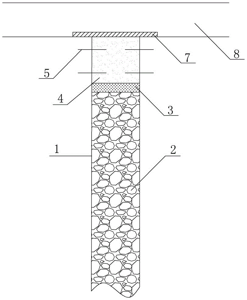
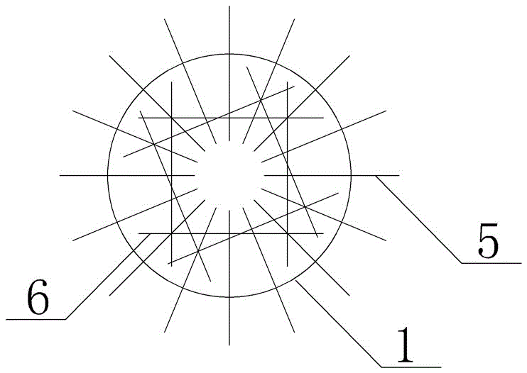
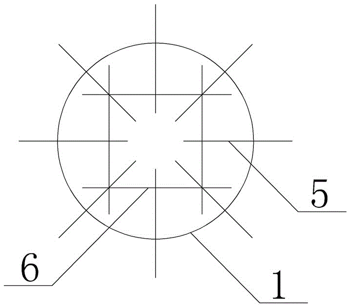
[0040]1) Prying: First, prying the mouth of the chute and the surroundings of the chute to be blocked in the descending section, tapping the rock with a crowbar, and prying off the rock with a dull and not crisp sound, so as to clean the pumice and ensure a safe and sound construction environment. Hidden dangers; 2) Ore filling in the chute: fill the chute with ore whose particle size does not exceed 1 / 8 of the diameter of the chute to 1.5m below the wellhead, level the filled ore, and lay a 0.1m cotton isolation layer; 3) Install anchor rods : An anchor hole with a depth of 0.7m is opened on the side wall of the chute between the isolation layer and the mouth of the chute, and the anchoring agent and the anchor rod are inserted into the anchor hole together. The length of the anchor rod is 1.5m, and the diameter is 20mm. On the side wall of the chute, there are two layers arranged in a horizontal ring, and there are four anchor rods in both layers. The distance between the two...

Embodiment 2

[0043] 1) Prying: First, prying the mouth of the chute and the surroundings of the chute to be blocked in the descending section, tapping the rock with a crowbar, and prying off the rock with a dull and not crisp sound, so as to clean the pumice and ensure a safe and sound construction environment. Hidden dangers; 2) Ore filling of the chute: fill the chute with ore whose particle size does not exceed 1 / 8 of the diameter of the chute to 5m below the wellhead, level the filled ore, and lay a 0.3m cotton isolation layer; 3) Install anchor rods: An anchor hole with a depth of 1.5m is opened on the side wall of the chute between the isolation layer and the mouth of the chute, and the anchoring agent and the anchor rod are inserted into the anchor hole together. The length of the anchor rod is 3m and the diameter is 20mm. There are two layers of horizontal circular rings on the side wall, and there are 20 anchor rods in both layers. The distance between the two layers of anchor rods...

Embodiment 3

[0046] 1) Prying: First, prying the mouth of the chute and the surroundings of the chute to be blocked in the descending section, tapping the rock with a crowbar, and prying off the rock with a dull and not crisp sound, so as to clean the pumice and ensure a safe and sound construction environment. Hidden dangers; 2) Ore filling of the chute: fill the chute with ore whose particle size does not exceed 1 / 8 of the diameter of the chute to 3m below the wellhead, level the filled ore, and lay a 0.2m cotton isolation layer; 3) Set the anchor rod: Open an anchor hole with a depth of 1m on the side wall of the chute between the isolation layer and the mouth of the chute, insert the anchoring agent and the anchor rod into the anchor hole, the length of the anchor rod is 2m, the diameter is 20mm, and the anchor rod is on the side of the chute There are two layers of horizontal circular rings on the wall, and 12 anchor rods are arranged on each layer. The distance between the two layers ...


PUM


Abstract

The invention discloses a chute descending segment plugging method and structure for effectively improving stability. The method includes the steps: 1) scaling an opening and the periphery of a chute, knocking rocks by a crowbar, prying the rocks with toneless and unclear sound by the crowbar, cleaning pumice stones and ensuring a safe construction environment without hidden danger; 2) filling the chute with ores, leveling the filling ores and laying an isolation layer; 3) setting anchor rods: forming anchor holes in the side wall of the chute between the isolation layer and the opening of the chute, inserting anchoring agents and the anchor rods into the anchor holes together, setting two layers of anchor rods on the side wall of the chute in a horizontally annular manner and embedding latticed strengthening steel into the anchor rods; 4) plugging the chute: pouring concrete into the chute within the range from the isolation layer to the opening of the chute, covering the chute with geotextile and performing maintenance after concrete pouring, finally, capping an ore plate completely covering the opening of the chute at the opening of the chute, and finishing plugging the chute.

Description

technical field [0001] The invention belongs to the technical field of mining technology and equipment, and in particular relates to a method and a structure for effectively improving the stability of a chute descending block. Background technique [0002] Because most of the mines are very high and the ore is transported frequently, in order to improve the transport efficiency and save costs, a pipeline similar to a well will be opened from top to bottom in the mine, and the ore will be directly dumped from top to bottom, which is called a slip shaft. The chute refers to the shaft that uses its own weight to slide ore or waste rock from top to bottom. On the one hand, it can improve the transportation efficiency, and on the other hand, it can play a certain role in crushing ore. Most of the chutes in the mining area are located inside the ore body and are vertically arranged next to the vein-piercing roadway. Several layers of the same ore block share a chute. The cutting ...

Claims


Application Information

Patent Timeline
Patent Type & Authority Applications(China)
IPC IPC(8): E21F15/00E21D20/02
CPCE21D20/02E21F15/00E21F15/005
Inventor 郎啟富李雪明包继锋吴锡煌余正方胡远徐万寿麦宗华张涛石绪红杨小平程传钊
Owner YUXI DAHONGSHAN MINING
Why Eureka
Try Eureka