Bearing cooling device

A cooling device and bearing technology, applied in the direction of bearing cooling, bearing components, shafts and bearings, etc., can solve the problems of increasing the water inlet flow of the cooling body, increasing the friction coefficient of the bearing bush, poor lubrication, etc., to solve the problem of frequent alarm and shutdown Problems or problems of burning pads, the friction coefficient of bearing pads is kept stable, and the effect of improving heat exchange efficiency

Pending Publication Date: 2017-05-31
郭远军
View PDF0 Cites 0 Cited by
  • Summary
  • Abstract
  • Description
  • Claims
  • Application Information

AI Technical Summary

Problems solved by technology

[0010] Since the existing cooling oil mainly adopts No. 46 turbine oil or No. 32 turbine oil, the optimum operating temperature range of No. 46 turbine oil is 44-46°C, and the optimum operating temperature range of No. 32 turbine oil is 38-40°C ;The existing cooling oil needs to be controlled below 65°C during the operation process. When the temperature of the cooling oil is too high, the viscosity becomes smaller, resulting in poor lubrication, the friction coefficient of the bearing pad becomes larger, the frictional heat generation is intensified, and the oil temperature rises rapidly, and The high oil temperature will aggravate the wear of the sliding friction surface; the existing bearing adopts this cooling structure. In order to prevent the oil temperature from being too high and causing the burning of the shoe, it is necessary to monitor the oil temperature in the bearing. When the temperature is high, it is necessary to increase cooling. When the temperature is too high, it will alarm and stop running
[0011] Because the existing bearing cooler structure generally has the problem of low heat exchange efficiency, the generator is prone to alarm shutdown, which not only affects the output efficiency and economic benefits of the power station, but also affects the use of other equipment in the power station during shutdown and start-up of the power station. Great impact on life expectancy
[0012] The main reason for the above problems is that the density and viscosity of the cooling oil are greatly affected by the change of oil temperature. The higher the temperature of the cooling oil, the smaller the density and viscosity. , the cooling oil with a large cooling capacity sinks, and the flow rate becomes smaller, and the cooling oil with a small cooling capacity floats up, causing the cooling oil with a large cooling capacity in the lower area of ​​the cooling oil chamber 101 to stay, while the cooling oil in the upper area is relatively small The flow rate of the cooling oil becomes faster and flows out from the cooling oil outlet 104, resulting in the high temperature of the cooling oil flowing out of the cooling oil outlet 104

Method used


Image

  • Bearing cooling device
  • Bearing cooling device
  • Bearing cooling device

Examples


Embodiment 1

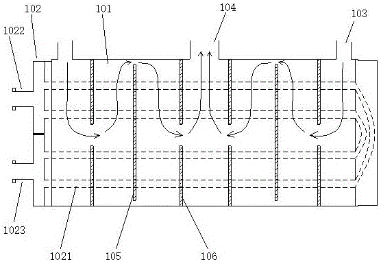
[0068] A bearing cooling device such as Figure 4 As shown, it includes a cooling chamber 1 and a cooling body 2, the cooling body 2 is located in the cooling chamber 1, and the cooling body 2 is coaxial with the cooling chamber 1; the cooling chamber 1 includes two hot oil inlets 11 and a cooling The oil outlet 12, the two thermal oil inlets 11 are respectively the first thermal oil inlet 111 and the second thermal oil inlet 112, the first thermal oil inlet 111 and the second thermal oil inlet 112 are respectively located at both ends of the cooling chamber 1, and the cold oil outlet 12 is located in the middle of the cooling chamber 1;

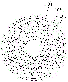
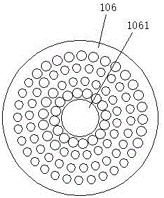
[0069] Such as Figure 4 As shown, the cooling body 2 includes a cooling pipe 21, a water inlet flange 22, an outlet flange 23, a bottom hole flow passage partition 3 and a top hole flow passage partition 4, and the cooling pipe 21 includes a water inlet 211 and a water outlet 212 , the water inlet 211 is connected to the water inlet flang...

Embodiment 2

[0076] A bearing cooling device such as Figure 7 As shown, it includes a cooling chamber 1 and a cooling body 2, the cooling body 2 is located in the cooling chamber 1, and the cooling body 2 is coaxial with the cooling chamber 1; the cooling chamber 1 includes two hot oil inlets 11 and a cooling The oil outlet 12, the two thermal oil inlets 11 are respectively the first thermal oil inlet 111 and the second thermal oil inlet 112, the first thermal oil inlet 111 and the second thermal oil inlet 112 are respectively located at both ends of the cooling chamber 1, and the cold oil outlet 12 is located in the middle of the cooling chamber 1;

[0077] Such as Figure 7 As shown, the cooling body 2 includes a cooling pipe 21, a water inlet flange 22, an outlet flange 23, a bottom hole flow passage partition 3 and a top hole flow passage partition 4, and the cooling pipe 21 includes a water inlet 211 and a water outlet 212 , the water inlet 211 is connected to the water inlet flang...

Embodiment 3

[0085] A bearing cooling device such as Figure 8 As shown, it includes a cooling chamber 1 and a cooling body 2, the cooling body 2 is located in the cooling chamber 1, and the cooling body 2 is coaxial with the cooling chamber 1; the cooling chamber 1 includes a hot oil inlet 11 and a cold oil The oil outlet 12, the hot oil inlet 11 and the cold oil outlet 12 are respectively located at both ends of the cooling chamber 1;

[0086] Such as Figure 8 As shown, the cooling body 2 includes a cooling pipe 21, a water inlet flange 22, an outlet flange 23, a bottom hole flow passage partition 3 and a top hole flow passage partition 4, and the cooling pipe 21 includes a water inlet 211 and a water outlet 212 , the water inlet 211 is connected to the water inlet flange 22, and the water outlet 212 is connected to the water outlet flange 23, and the water inlet flange 22 and the water outlet flange 23 are located on the side of the cooling chamber 1; the cooling body 2 includes at le...


PUM


Abstract

The invention discloses a bearing cooling device. The bearing cooling device comprises a cooling chamber and a cooling body. A hot oil inlet and a cold oil outlet are formed in the cooling chamber, the cooling body is located in the cooling chamber, the cooling body and the cooling chamber are coaxial, and the cooling body comprises a cooling pipe, a water inlet flange, a water outlet flange, a bottom hole runner partition plate and a top hole runner partition plate; the water inlet end of the cooling pie is connected to a water inlet flange, the water outlet end of the cooling pipe is connected to a water outlet flange, perforated holes for inserting the cooling pipe are distributed in the surfaces of the bottom hole runner partition plate and the top hole runner partition plate, and the bottom hole runner partition plate and the top hole runner partition plate are distributed in the cooling chamber between the hot oil inlet and the cold holt outlet in a spaced manner. The bearing cooling device disclosed by the invention has relatively high heat exchange efficiency. Compared with an existing cooler, the oil temperature can be reduced by about 8-20 DEG C, alarming and stopping due to excessive high oil temperature can be effectively prevented, and a bush wearing or bush burning phenomenon due to excessively high temperatures of the bearing bush and the cooling oil can be effectively avoided.

Description

technical field [0001] The invention relates to the field of bearing devices, in particular to a bearing cooling device for a hydraulic generator. Background technique [0002] The bearing cooler is one of the important parts of the hydro-generator. Its function is to establish a thermal dynamic balance through the heat exchange between the bearing friction heat and the cooler, and stabilize the temperature of the bearing bush in the normal operating range. [0003] The heat exchange medium used in the existing bearing cooler mainly adopts liquid oil, and the liquid oil circulates through the bearing bush and the cooling part to remove the frictional heat of the bearing bush. [0004] Bearing coolers commonly used in existing hydroelectric generators, such as the attached figure 1 As shown, it includes a cooling oil chamber 101, a cooling body 102, a hot oil inlet 103, a cold oil outlet 104, an edge ring flow channel partition 105 and a central flow channel partition 106, a...

Claims


Application Information

Patent Timeline
IPC IPC(8): F16C37/00F03B11/06
CPCF03B11/06F16C37/00Y02E10/20
Inventor 郭远军
Owner 郭远军
Why Eureka
Try Eureka