hybrid clutch

A clutch and hybrid technology, applied in clutches, friction clutches, mechanical drive clutches, etc., can solve the problems of low transmission efficiency and loose transmission ratio of friction clutches.

Inactive Publication Date: 2019-04-09
713 RES INST OF CHINA SHIPBUILDING IND CORP
View PDF6 Cites 0 Cited by
  • Summary
  • Abstract
  • Description
  • Claims
  • Application Information

AI Technical Summary

Problems solved by technology

[0003] The technical problem to be solved by the present invention is: the friction clutch has the disadvantages of lax transmission ratio and low transmission efficiency, while the rigid clutch has a fixed transmission ratio and does not generate frictional heat, but has the disadvantage that it can only be engaged at a standstill or at a low speed. In order to solve the above problem, providing a hybrid clutch

Method used


Image

  • hybrid clutch

Examples


Embodiment Construction

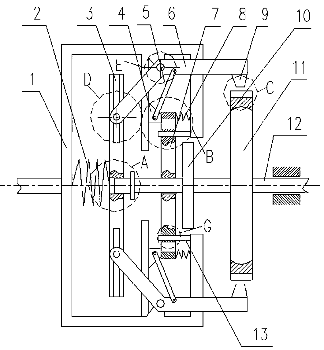
[0015] Such as figure 1 As shown, the hybrid clutch includes a driven disc 1 connected to the driven shaft, and also includes an active friction coupling 10 and a rigid coupling 11 connected to the driving shaft 12. The driven disc 1 is provided with a driven friction coupling 7 And the driven rigid coupling. In the initial state, the active friction coupling 10 on the driving shaft 12 is combined with the driven friction coupling 7 in the driven disk 1. When the driving shaft 12 rotates at a high speed, the driving shaft 12 is moved to make the rigid coupling Part 11 is combined with the driven rigid joint, and at the same time, the active friction joint 10 is separated from the driven friction joint 7 .

[0016] The active friction joint 10 and the rigid joint 11 are sequentially arranged on the driving shaft 12 , and a stop ring is provided at the front end of the driving shaft 12 .

[0017] The driven disk 1 includes a lower part and an end part, the cross section of the ...


PUM


Abstract

The invention relates to a hybrid type clutch, and belongs to the field of mechanical design. The hybrid type clutch comprises a driven disk connected with a driven shaft, and further comprises a driving friction combination piece and a rigid combination piece which are connected with a driving shaft, wherein a driven friction combination piece and a driven rigid combination piece are arranged in the driven disk; under an initial state, the driving friction combination piece on the driving shaft is combined with the driven friction combination piece in the driven disk; and when rotating at high speed, the driving shaft is moved to enable the rigid combination piece to be combined with the driven rigid combination piece and enable the driving friction combination piece to be separated from the driven friction combination piece. Compared with the prior art, the hybrid type clutch aims to realize steady combination and efficient transmission of the clutch; the steady combination is realized through friction at the combination front end of the clutch; and when the driving shaft rotates at the high speed, the clutch carries out rigid combination and friction combination piece separation to realize efficient transmission, so that the friction energy consumption and friction heat are substantially reduced.

Description

technical field [0001] The invention relates to a hybrid clutch and belongs to the field of mechanical design. Background technique [0002] The clutch is a device located between the power input mechanism and the power output mechanism, which controls the on-off of the power output through engagement and separation. It is widely used in machine tools, ships, vehicles, presses and other mechanical devices. Classified according to the way of engaging parts, commonly used clutch structures are mainly divided into friction engagement and rigid engagement. The friction clutch has a simple structure and can engage smoothly under high speed difference, but has the disadvantages of loose transmission ratio and low transmission efficiency. The transmission ratio of the rigid clutch is fixed and does not generate frictional heat, but it has the disadvantage that it can only be engaged at a standstill or at a low speed. In order to make the clutch obtain high transmission efficiency...

Claims


Application Information

Patent Timeline
Patent Type & Authority Patents(China)
IPC IPC(8): F16D13/38F16D13/70F16D13/60F16D13/58
CPCF16D13/38F16D13/58F16D13/60F16D13/70
Inventor 李猛付彩越彭松江王琳琳李伟牛延鹏刘建张瑛范永
Owner 713 RES INST OF CHINA SHIPBUILDING IND CORP
Why Eureka
Try Eureka