A New Type of Positive and Negative Stiffness Parallel Low Frequency Vibration Isolation Mechanism
A positive and negative stiffness, negative stiffness technology, applied in the field of new positive and negative stiffness parallel low-frequency vibration isolation mechanism, can solve the problems of poor adaptability to working conditions, poor flexibility, low stability, etc., achieve good stiffness characteristics, convenient installation and transportation, The effect of improving adaptability
- Summary
- Abstract
- Description
- Claims
- Application Information
AI Technical Summary
Problems solved by technology
Method used
Image
Examples
Embodiment 1
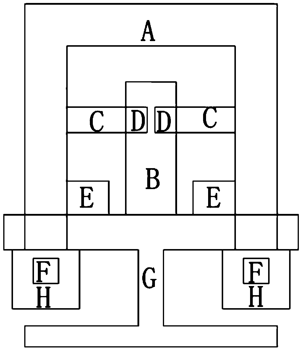
[0068] Such as figure 1 As shown, it is a block diagram of the system composition structure of a novel positive and negative stiffness parallel low-frequency vibration isolation mechanism in the present invention and this embodiment. Among them, the connection relationship of each component module is as follows:
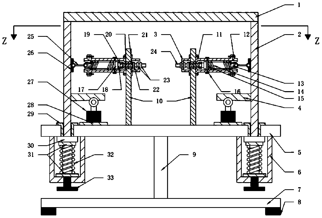
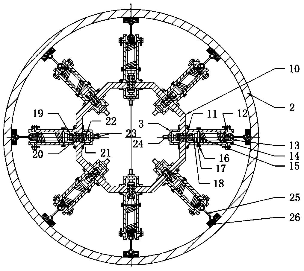
[0069] The lower end of the load-bearing structure A is connected with the support and fixed structure of the base; the horizontal spring support column B is fixed on the upper surface of the support and fixed structure G of the base; The negative stiffness spring adjustment device D on the inner side of B is connected, and the other end is hinged with the load-bearing structure A; the damping structure E is fixed on the upper end surface of the base support fixed structure G and connected with the cylinder side wall of the load-bearing structure A, and the positive stiffness spring adjustment device H Fixed on the lower end surface of the base supporting and fixing...
Embodiment 2
[0077] Figure 8 Shown is a schematic structural diagram of a novel positive and negative stiffness parallel low-frequency vibration isolation mechanism of this embodiment. Basically similar to Example 1, the difference is that the adjustment knob 33 is used in conjunction with the spoke pressure sensor 30 (such as Figure 7 shown) to adjust the static balance position of the vibration isolation mechanism, and ensure the accuracy and consistency of the adjustments of all vertical springs.
[0078] If the load-bearing quality of the system changes, the horizontal spring connecting rod 25 is not in a horizontal state at the static equilibrium position of the system. At this time, the adjustment knob 33 can be rotated and used in conjunction with the spoke pressure sensor 30 to make the adjustments of several vertical springs accurate and consistent. . Move the static equilibrium position of the system so that when the system is in the static equilibrium position, the horizonta...
Embodiment 3
[0080] Figure 9 Shown is a schematic structural diagram of a novel positive and negative stiffness parallel low-frequency vibration isolation mechanism of this embodiment. Basically similar to Example 1, the difference is that the compression spring adjustment nut 22 is used in conjunction with the S-type pressure sensor 17 (such as Image 6 shown), adjust the pressure of the compression spring main body, thereby continuously adjusting the pre-compression of the horizontal spring main body 14, and ensure the accuracy and consistency of the pre-compression of several horizontal springs. After the adjustment of the pre-compression amount of the main body of the horizontal spring is completed, the proximal sliding block 15 of the horizontal spring is fixed by the fixing screw 16 of the proximal sliding block of the horizontal spring. By controlling the pre-compression of the horizontal spring body, the negative stiffness characteristic range of the system can be adjusted. When...
PUM
 Abstract
Description
Claims
Application Information
 - R&D
- Intellectual Property
- Life Sciences
- Materials
- Tech Scout
- Unparalleled Data Quality
- Higher Quality Content
- 60% Fewer Hallucinations
Browse by: Latest US Patents, China's latest patents, Technical Efficacy Thesaurus, Application Domain, Technology Topic, Popular Technical Reports.
© 2025 PatSnap. All rights reserved.Legal|Privacy policy|Modern Slavery Act Transparency Statement|Sitemap|About US| Contact US: help@patsnap.com


