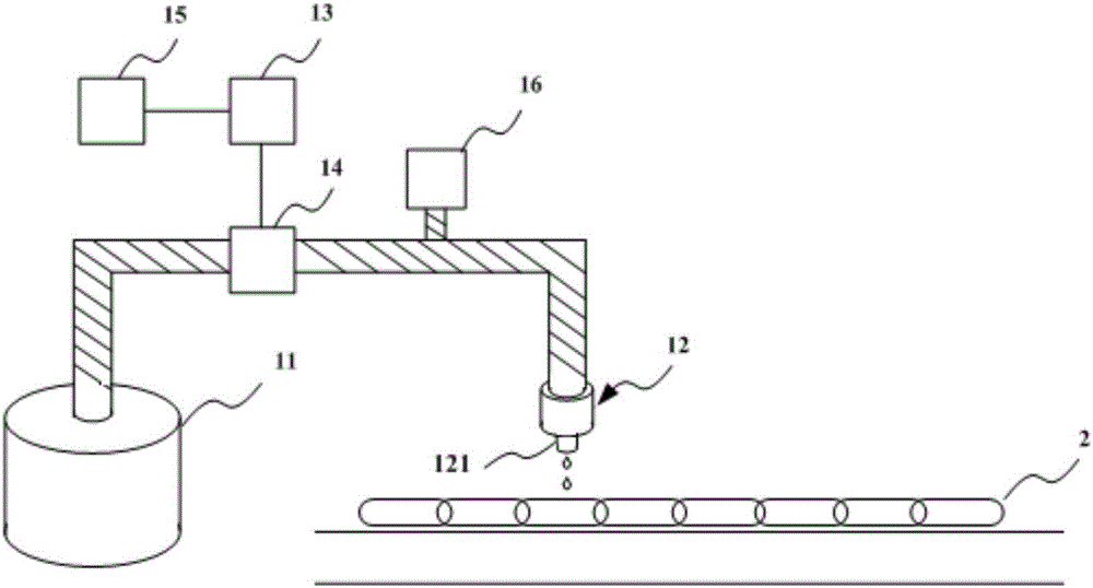
Equipment lubricating system

A lubrication system and equipment technology, applied in the field of industrial manufacturing, can solve the problems of uncontrollable oil volume, failure to achieve automatic oiling and lubrication, waste of man-hours and other problems, and achieve the effect of simplifying daily maintenance work and high oiling efficiency

Inactive Publication Date: 2017-05-31
INVENTEC PUDONG TECH CORPOARTION +1
View PDF10 Cites 5 Cited by
  • Summary
  • Abstract
  • Description
  • Claims
  • Application Information

AI Technical Summary

Problems solved by technology

[0004] However, there are many deficiencies in the current refueling method. For example, the drip is intermittent. For the chain transmission mechanism, there will be omissions in the frequency band refueling, and the degree of lubrication is insufficient; and the manual injection has no fixed periodicity, which cannot achieve automatic refuelin

Method used


Image

  • Equipment lubricating system
  • Equipment lubricating system
  • Equipment lubricating system

Examples


Embodiment Construction

[0037] Embodiments of the present invention are described below through specific examples, and those skilled in the art can easily understand other advantages and effects of the present invention from the content disclosed in this specification. The present invention can also be implemented or applied through other different specific implementation modes, and various modifications or changes can be made to the details in this specification based on different viewpoints and applications without departing from the spirit of the present invention. It should be noted that, in the case of no conflict, the following embodiments and features in the embodiments can be combined with each other.

[0038] It should be noted that the diagrams provided in the following embodiments are only schematically illustrating the basic ideas of the present invention, and only the components related to the present invention are shown in the diagrams rather than the number, shape and shape of the compo...


PUM


Abstract

The invention provides an equipment lubricating system which comprises at least one lubricating agent container, at least one nozzle assembly, an electric control device and a timing module. The lubricating agent container is used for storing lubricating agents. At least one nozzle assembly communicates with the lubricating agent container for the lubricating agents to flow towards the nozzle assembly from the lubricating agent container. The electric control device receives a rail starting signal. An electromagnetic valve is arranged between the lubricating agent container and a nozzle and is electrically connected with the electric control device. The timing module is electrically connected with the electromagnetic valve and the electric control device. When the electric control device receives the rail starting signal, the timing module starts to conduct timing and generate a timing value, when the timing value reaches the first preset threshold value, the electromagnetic valve is opened so that the lubricating agents in the lubricating agent container can be sprayed out through the nozzle assembly, when the timing value reaches the second preset threshold value, the electromagnetic valve is closed, the nozzle assembly is stopped from spraying the lubricating agents, and the timing module conducts timing again. According to the equipment lubricating system, the lubricating agents are quantitatively injected to equipment rails periodically, and the oil injection efficiency is high.

Description

technical field [0001] The invention is applied in the technical field of industrial manufacturing, and in particular relates to equipment lubrication systems. Background technique [0002] With the rapid development of mechanization, automated machinery is favored by various fields. The increase in the degree of automation has reduced manpower operations and brought great economic benefits to manufacturers. However, the introduction of automation will undoubtedly increase the maintenance man-hours of equipment and the loss of equipment hardware. [0003] For transmission chains and bearings, regular lubrication is required to reduce the wear and tear of the hardware during non-stop operation. At present, there are imported refueling devices for equipment lubrication (such as drip refueling, manual injection and continuous refueling) on ​​the market. [0004] However, there are many deficiencies in the current refueling method. For example, the drip is intermittent. For th...

Claims


Application Information

Patent Timeline
IPC IPC(8): F16N7/38F16H57/05B65G45/08
CPCF16N7/385B65G45/08F16H57/0456F16H57/05
Inventor 张孝勇
Owner INVENTEC PUDONG TECH CORPOARTION
Why Eureka
Try Eureka